Engine starter

A technology of engine starting and engine, which is applied in the direction of engine starting, engine motor starting, engine components, etc., and can solve problems such as the inability to reduce the rated output power of the motor, increase the cost of the device, and cannot have sufficient boosting intervals, etc.

Inactive Publication Date: 2004-01-07
MITSUBA CORP
View PDF0 Cites 20 Cited by
  • Summary
  • Abstract
  • Description
  • Claims
  • Application Information

AI Technical Summary

Problems solved by technology

[0006] However, although the crankshaft angle (piston position) in the engine stop state can be roughly estimated, it cannot always be said to be the same. When setting the reverse drive amount taking into account the error, there is usually not a suffici

Method used


Image

  • Engine starter
  • Engine starter
  • Engine starter

Examples


Embodiment Construction

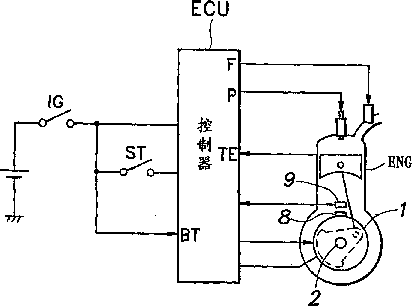
[0042] figure 1 It is a schematic configuration diagram of an engine starting device to which the present invention is applied. Such as figure 1 As shown, the electric motor (generator) 1 of this starting device is set under the state of being directly connected coaxially with the crankshaft 2 of the four-stroke engine ENG, and is used as a generator while rotating the power output shaft at the time of starting. Used while the engine is running. Then, signals from an ignition switch IG and a starter switch ST are input to a controller ECU that controls the electric motor 1 and the engine ENG. Then the ignition signal P and the fuel injection signal F are output from the controller ECU to the engine ENG.

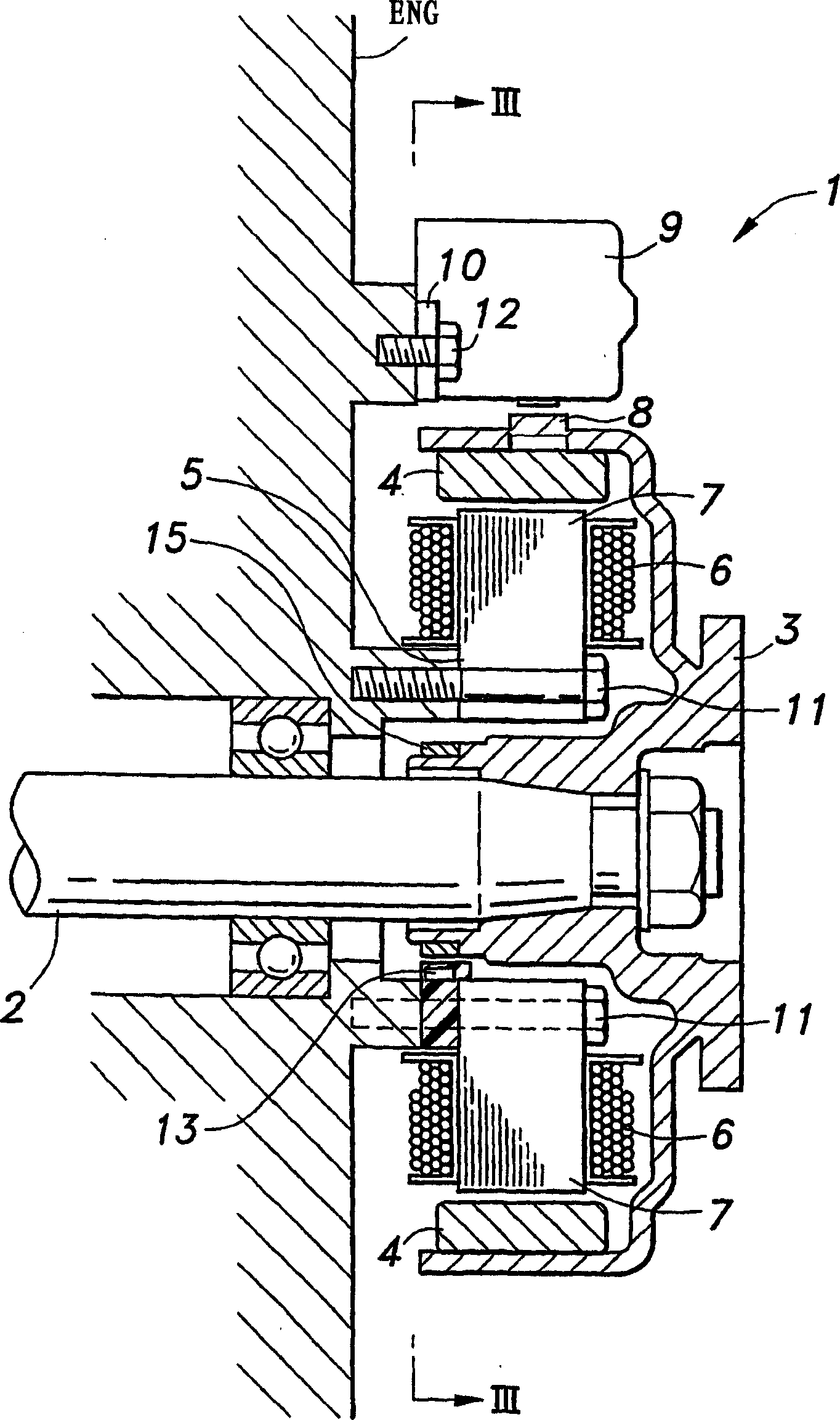
[0043] refer to figure 2 and image 3 The structure of the generator 1 will be described as follows. As shown in the figure, the electric motor 1 is coaxially fixed on the crankshaft 2 of the engine ENG, and a flat bottomed cylindrical outer rotor 3 that doubles as a f...


PUM


Abstract

An engine starter capable of cranking a crankshaft finally in forward direction after driving in revere direction, wherein a motor is energized so as to be intermittently rotated in forward direction before the driving in reverse direction at least under specified conditions so that assured start can be performed at all times, whereby, as necessary, the crankshaft (piston) can be moved to an optimum position and, in addition, this control can be realized without using any special angle sensor.

Description

technical field [0001] The present invention relates to engine starting devices. Background technique [0002] Conventionally, in automobiles, the power output shaft is rotated by an electric motor, and the electric motor is used as a generator. In this way, the starter and the generator can be used both with one electric motor, thereby simplifying the auxiliary equipment of the engine. [0003] In the starting device, since the position of the piston is not fixed when the engine is started, it must be able to start from the state of stopping at the position just before the compression stroke, and it can also be reliably started in a cold state such as viscous resistance. Therefore, It is necessary to consider increasing the output power of the motor, so there is a problem of increasing the size of the motor. [0004] In order to start under the above-mentioned conditions even if the output power of the electric motor is small, it is sufficient to make a swing type starter...

Claims


Application Information

Patent Timeline
IPC IPC(8): F02D41/34F02N5/04F02N11/04F02N11/08
CPCF02N5/04F02N19/005F02N2300/104F02D2041/2017F02N11/0859F02N11/04F02N2019/007F02D41/009F02N11/087F02N11/0814F02D2250/06F02D2041/2027
Inventor 稻叶光则行森公雄金子义弘野末裕
Owner MITSUBA CORP
Why Eureka
Try Eureka