Apparatus for rotary working to material

A rotating axis, facing technology, applied in the field of devices for processing materials, capable of solving problems such as low tear resistance

Inactive Publication Date: 2004-01-28
HEIDELBERGER DRUCKMASCHINEN AG
View PDF4 Cites 3 Cited by
  • Summary
  • Abstract
  • Description
  • Claims
  • Application Information

AI Technical Summary

Problems solved by technology

This results in lower tear resistance for these s

Method used


Image

  • Apparatus for rotary working to material
  • Apparatus for rotary working to material
  • Apparatus for rotary working to material

Examples


Embodiment Construction

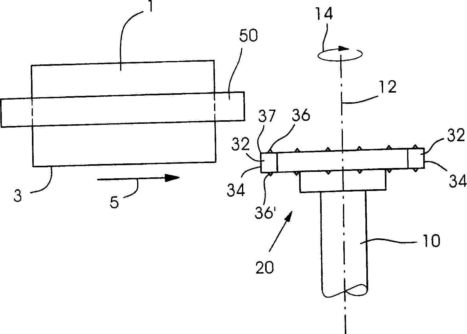
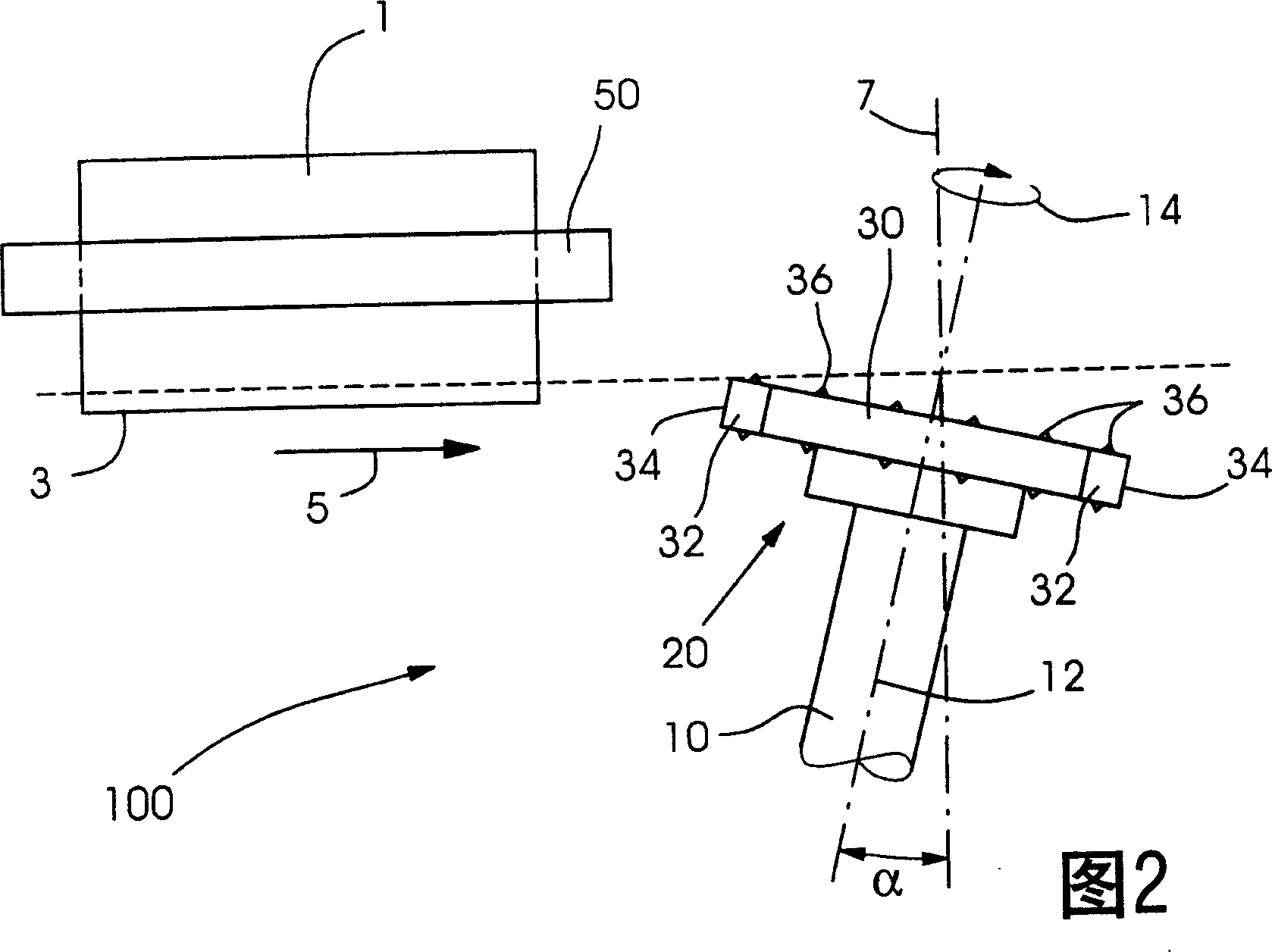
[0038] figure 1 The basic or practical principle of the device 100 of the invention during the processing of the material 1 is shown. Material 1 is a stack of sheet-like printing material in the described embodiment.

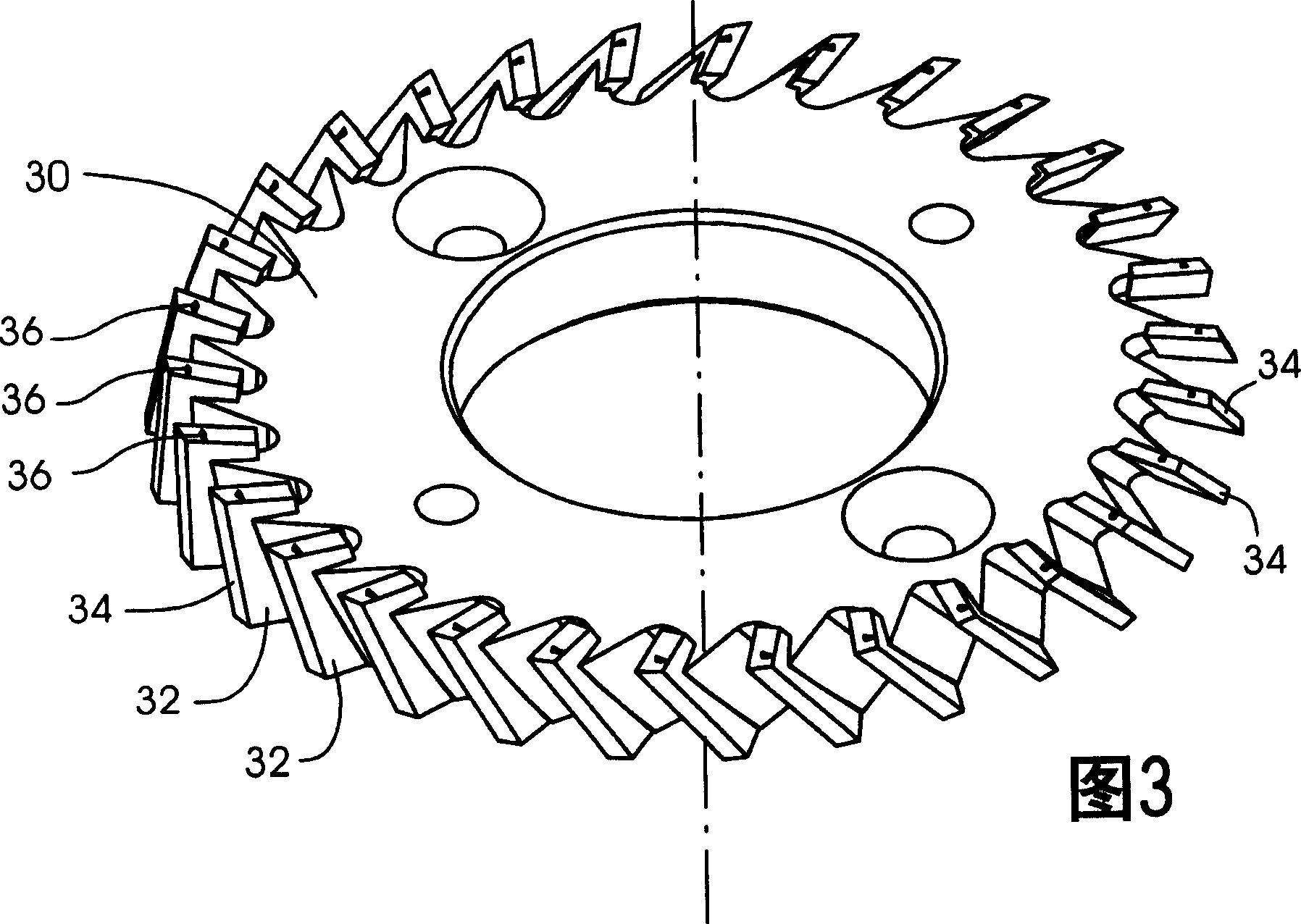
[0039] A stack of sheet-like printing material 1 with a common side 3 is conveyed towards the cutter head 20 in the direction of movement indicated by the reference symbol 5 . The stack of sheet-like printing materials is prevented from unraveling by the clamping element 50 . The clamping member 50 also helps to ensure that the sheets of printing material 1 do not slip within the stack due to the shear stresses generated. The cutter head 20 is positioned with its processing element 32 along the direction of movement of the sheet-like printing material 1 . The tool head 20 rotates about an axis of rotation 12 and the axis of rotation 12 forms an angle α with the perpendicular 7 of the cutting plane 9 , as shown in FIG. 2 . The axis of rotation 12 and the vert...


PUM


Abstract

A device treats a side edge of the pile of a body to be printed which makes a cutting face move along the direction of movement and is provided with a tool head supporting a cutting ring which is rotated around a rotary shaft. A plurality of a treating member are arranged at the circumference of the cutting ring and the member has at least one cutting part which cuts the material in order. The cutting part has at least one cutting corner, turning to the material, which defines the cutting face. At least one of the treating member has at least one notching part which is turning to the material in view toward the axial direction and projecting across the cutting corner on the cutting face.

Description

technical field [0001] The invention relates to a device for processing material according to the preamble of claim 1, in particular for processing the side edges of sheet-like printed material arranged in stacks to be adhesively bound (adhesive binding). processing device. Glue binding is often used to bind the pages of a book or brochure with a small print run. In particular, glue binding is used to finish digital prints and booklets due to the exceptionally small print runs involved in the above process (eg, when only one volume is produced). Background technique [0002] For glue binding production, the sheets of printed material that will eventually form a bound book or booklet are first collected and aligned together into a stack. The stack of printed materials is clamped to prevent the sheets from slipping within the stack. Next, one page of the stack of printed materials is first leveled and coated with a suitable adhesive. Various hot and cold glues or so-called...

Claims


Application Information

Patent Timeline
IPC IPC(8): B23C5/08B42C5/04B65H35/08
CPCB42C5/04B23C5/08Y10T83/0524Y10T83/9372Y10T83/242Y10T83/942
Inventor 拖马斯·德拉赫尔穆特·多梅斯米夏埃多·弗罗因德弗兰克·格吕内贝格安德烈亚斯·施魏策尔
Owner HEIDELBERGER DRUCKMASCHINEN AG
Why Eureka
Try Eureka