
Rail

A track and rail waist technology, applied in the field of railway track, can solve the problems of narrow available space, track wear, track vibration, etc., achieve broadband vibration reduction effect, improve service life, and good vibration reduction effect

Inactive Publication Date: 2004-01-28
尹学军
View PDF1 Cites 13 Cited by
  • Summary
  • Abstract
  • Description
  • Claims
  • Application Information

AI Technical Summary

Problems solved by technology

However, the wheel is a high-speed rolling part, and the rail is a very long continuum. Both of them have relatively complex shapes, the available space nearby is small, and the strength and force are large. General elastic materials such as ordinary rubber and work in the elastic zone None of the metallic lead can provide sufficient effective damping
This situation has caused technical problems such as track vibration, track primary noise and track wear, which have puzzled those skilled in the art for a long time and cannot be solved.

Method used


Image

  • Rail
  • Rail
  • Rail

Examples


Embodiment 1

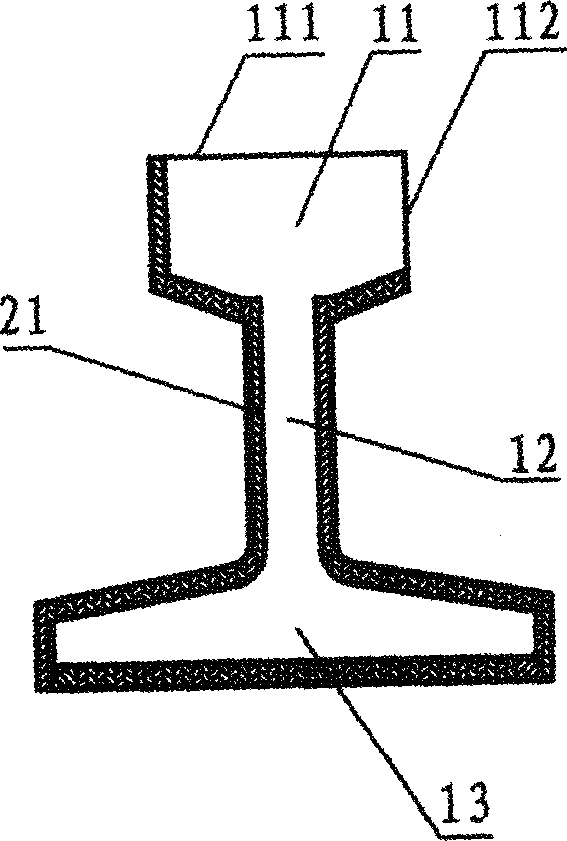
[0029] track of the present invention, see figure 1 , which includes a track body, which is composed of a rail head 11, a rail waist 12 and a rail bottom 13, and a layer of solid high damping is arranged on the non-working outer surface of the track body except the rail head top surface 111 and the side working surface 112 Material 21. The solid high-damping material is specifically made of high-damping modified asphalt that is solid at room temperature, and is made of rubber powder, talcum powder, mica powder, etc., and a layer of high-strength fiber mesh is embedded in the middle to make a damping coil. , hereinafter referred to as modified asphalt damping membrane. The solid high-damping material is a viscoelastic solid at normal temperature, and becomes a viscous liquid after heating, and can be integrated with the track body through self-adhesive, hot-melt bonding or thermal coating.

[0030] For the track of this structure, when the train is running, the vibration gene...

Embodiment 2

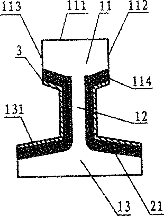
[0032] see figure 2, on the surface of the constraining structure 3, it is usually a relatively rigid aluminum plate or color steel plate, which is bent or rolled into a profile with a cross section similar to that of the rail waist 12, rail jaw 114 and rail bottom surface 131, or engineering plastic extrusion The profile, that is, the restraint plate, is hot-melted and pasted with two layers of solid high-damping material 21, which is still a modified asphalt damping coil, and made into a damping structure, and then the rail waist 12, rail jaw 114 and rail jaw 114 on the non-working surface of the track body The upper surface 131 of the rail bottom is directly hot-melt bonded to the rail body.

Embodiment 3

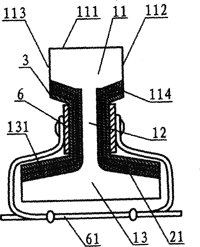
[0034] see image 3 , the difference from Example 2 is that the high damping material is two layers of high damping rubber, which is vulcanized together with the restraint plate in the factory to make a damping structure, which is tightly compressed by the clamping parts 6 arranged on both sides of the rail waist 12 on both sides of the track body. The clamping part 6 is a C-shaped hoop that wraps around the bottom of the rail between the rail ties, and it can also be an extension of the rail fastener spring to the rail waist, or a bolt that penetrates the rail waist.

[0035] Embodiments 1-3 can be implemented in factory production or on-site, but embodiment 3 is relatively more suitable for rapid on-site implementation. If it is produced in the factory, the restraint plate and the track body are directly vulcanized into one with high damping rubber, without clamping parts, and the vibration reduction effect is better.


PUM


Abstract

The present invention relates to a track structure for railroad or electric tramway. It incldues track self-body, on the non-working surface of said track self-body a damping body made of damping material is set, and this trackway with damping structure can absorb the vibration and noise produced by trackway when train is running on the trackway, specially, the first noise can be greatly absorbedby damping body, so that the production of the secondary noise can be naturally reduced. Said invention structure not only can reduced noise, but also can prolong the service life of track.

Description

technical field [0001] The invention belongs to railway tracks, in particular to a track structure for railways or tramways, specifically railways, subways, urban railways, elevated light rails, high-speed railways and the like. Background technique [0002] With the modern development of transportation technology, there are more and more urban rail transits such as subways and elevated light rails. While bringing convenience to urban residents, they also bring different degrees of vibration and noise disturbance to residents along the lines. According to the current theory and practice, the vibration is mainly transmitted to the ballast bed through the track contact, and then transmitted to the foundation or tunnel wall or bridge to the pier through the ballast bed, and then transmitted to the surrounding buildings through the soil, generating vibration and solid sound transmission in the building, form interference. Noise is divided into primary n...

Claims


Application Information

Patent Timeline
IPC IPC(8): E01B19/00
CPCE01B19/003
Inventor 尹学军钱国桢
Owner 尹学军
Features
  • Generate Ideas
  • Intellectual Property
  • Life Sciences
  • Materials
  • Tech Scout
  • Unparalleled Data Quality
  • Higher Quality Content
  • 60% Fewer Hallucinations
Learn More