
Thermally and mechanically stable low-cost high thermal conductivity structure for single-mode fiber coupling to laser diode

A technology of laser diodes and optical fibers, which is applied in the field of high thermal conductivity structures, and can solve problems such as loss of optical fiber coupling efficiency

Inactive Publication Date: 2004-02-11
POWERNETIX
View PDF0 Cites 11 Cited by
  • Summary
  • Abstract
  • Description
  • Claims
  • Application Information

AI Technical Summary

Problems solved by technology

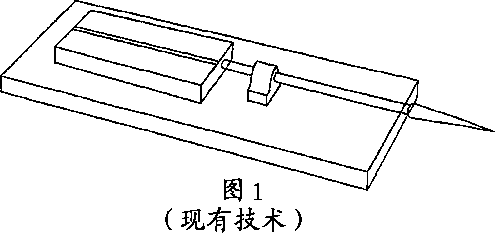
Consequently, an asymmetric temperature gradient occurs, resulting in a thermally induced loss of fiber coupling efficiency

Method used


Image

  • Thermally and mechanically stable low-cost high thermal conductivity structure for single-mode fiber coupling to laser diode
  • Thermally and mechanically stable low-cost high thermal conductivity structure for single-mode fiber coupling to laser diode
  • Thermally and mechanically stable low-cost high thermal conductivity structure for single-mode fiber coupling to laser diode

Examples


Embodiment Construction

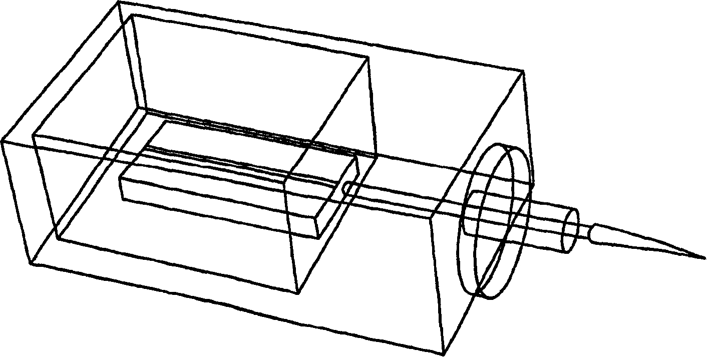
[0050] Now refer to the attached picture Exemplary embodiments of the present invention will be described. see Figure 4 , structure 10 combines optical tube 12, fiber holder 14, laser diode 16, and heat sink 18 in alignment with optical axis 20 into a generally rigid assembly that can be placed within a larger fiber optic package. Such as Figure 5 As shown in , the fiber holder 14 is generally spherical in shape but may have flat end faces 27,29. The fiber holder 14 has a central bore 15 aligned with the optical axis 20 and receiving an optical fiber 24 . The central bore 22 has a reduced diameter near the end 26 where the fiber fits into or emerges from the fiber holder 14 to provide a secure fit for the tip 28 of the optical fiber 24 . The fiber tip 28 is metallized so that the fiber tip 28 can be soldered into place when the fiber 24 is inserted into the central bore 22 . The surface of the fiber can be polished flush with the flat end face 29 of the fiber holder 14,...


PUM


Abstract

A structure that allows both axial and radial alignment between a laser diode (16) and optical fiber (24) to be achieved in a single attachment process. The structure incorporates an optics tube (12), fiber holder (14), laser diode (16), and heat sink (18). The fiber holder (14)is affixed to the inside surface at one end of the optics tube (12) and retains a segment of fiber in axial alignment with and close proximity to the laser diode. The heat sink is placed into the opposite end of the optics tube (12) and serves to draw energy in the form of heat away from the laser diode. The laser diode is powered via an electrical lead that attaches to a metalized ceramic substrate located between the laser diode and the heat sink. The symmetrical design of the structure is rigid and substantially insensitive to thermal and mechanical stress that cause misalignment in planar designs of similar dimensional proportion. The optics tube (12) and heat sink elements of the structure are substantially cylindrical in shape to allow high precision parts, as the heat sink and optics tube (12) are easily turned and abrasively finished using standard machining equipment.

Description

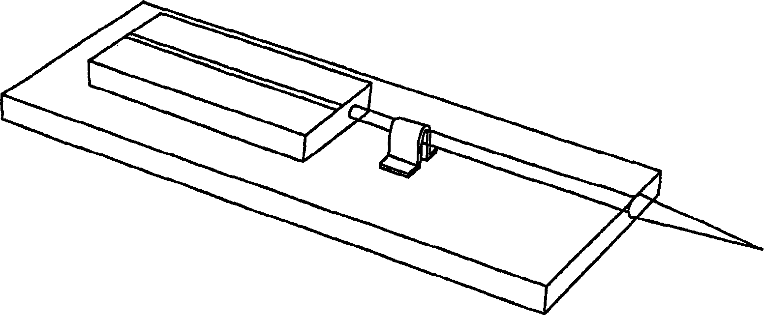
[0001] related application [0002] This application claims the benefit of U.S. Provisional Application Serial No. 60 / 236,934, filed September 28, 2000, and U.S. Utility Priority to Application Serial No. 09 / 880,980, which applications are incorporated herein by reference. technical field [0003] The present invention relates generally to structures and methods for coupling optical fibers to laser diodes, and more particularly to thermally and mechanically stable high thermal conductivity structures and methods for coupling. Background technique [0004] The three most common techniques used to align and secure singlemode fibers to high power laser diodes are soft solder fiber locking, omega yoke laser welding, and laser welding with individual X / Y and Z alignment axial design. Technologies employing organic adhesives as a means of securing fibers are generally unsatisfactory because of thermal mismatch issues, mechanical stability issues, and laser reliability issues. A...

Claims


Application Information

Patent Timeline
IPC IPC(8): G02B6/42
CPCG02B6/4226G02B6/4238G02B6/4202G02B6/4204G02B6/4237G02B6/424G02B6/4269G02B6/4271G02B6/4274
Inventor 戴维·M·罗斯
Owner POWERNETIX
Learn More