Device and method for improving wavefront quality of atmosphere laser communication link

An atmospheric laser communication and wavefront technology, applied in the field of laser communication, can solve the problems of limited bandwidth and accuracy of correction algorithm, correction signal, low communication code rate, etc., and achieve high heterodyne efficiency and single-mode fiber coupling efficiency, The optical path structure is compact and efficient, and the effect of high compensation accuracy

Active Publication Date: 2015-05-13
上光通信技术(上海)有限公司
View PDF11 Cites 10 Cited by
  • Summary
  • Abstract
  • Description
  • Claims
  • Application Information

AI Technical Summary

Problems solved by technology

Although this technology has been successfully verified in the communication link between satellites, it faces a severe test in the atmospheric link between the satellite and the ground
In 2011, Harbin Institute of Technology successfully realized the first satellite-ground laser communication link in China. Although the non-coherent communication technology was less affected by atmospheric turbulence, the communication code rate was very low and could not fully reflect the advantages of laser communication.
However, since the time variation of atmospheric turbulence can reach hundreds of Hz, it is difficult for the adaptive system to obtain high correction accuracy in such a high loop bandwidth. If the system bandwidth is reduced, the distortion of the signal wavefront cannot be completely corrected in time. For communication systems with bit rates as high as Gbit / s, this will introduce a large number of bit errors
Therefore, limited by the bandwidth and correction algorithm of the control system and the accuracy of the Hartmann wavefront sensor, the method of purely using the adaptive optics system for wavefront correction is not ideal for coherent laser communication systems

Method used


Image

  • Device and method for improving wavefront quality of atmosphere laser communication link
  • Device and method for improving wavefront quality of atmosphere laser communication link
  • Device and method for improving wavefront quality of atmosphere laser communication link

Examples


Embodiment Construction

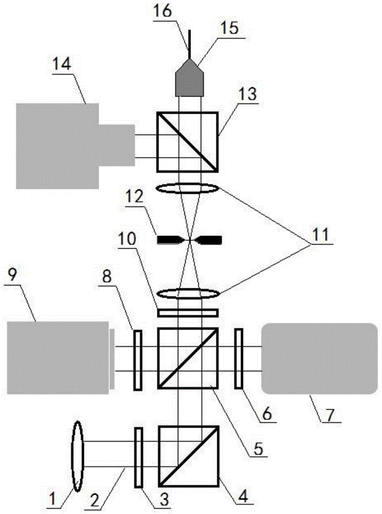
[0028]see figure 2 , figure 2 It is a schematic diagram of a device for improving beam wavefront quality in a coherent laser communication atmospheric link of the present invention. As can be seen from the figure, the device for improving the beam wavefront quality of the atmospheric laser communication link in the present invention comprises a collimating eyepiece 1 at the receiving end on the ground, and along the direction of the signal beam 2 output by the collimating eyepiece 1 are the first half-wave plate 3 and the first half-wave plate 3 and the first A polarization beam splitter 4, the second polarization beam splitter 5, the second half-wave plate 10, the optical 4f system 11, the third polarization beam splitter 13, the single-mode Fiber coupler 15 and single-mode fiber 16, on the right side of the second polarization beam splitter 5 are the first quarter-wave plate 6 and fast mirror 7, and on the left side of the second polarization beam splitter 5 It is the se...


PUM


Abstract

The invention provides device and method for improving wavefront quality of an atmosphere laser communication link. The device comprises a collimating eyepiece at the ground receiving end; a first half-wave plate and a first polarization beam splitter are sequentially arranged in the signal beam output direction of the collimating eyepiece; a second polarization beam splitter, a second half-wave plate, an optical 4f system, a third polarization beam splitter, a single-die fiber coupler and a single-die fiber are sequentially arranged in the reflecting light direction of the first polarization beam splitter; a first 1 / 4 wave plate and a quick reflector are sequentially arranged at the right of the second polarization beam splitter; a second 1 / 4 wave plate and a deformation mirror are sequentially arranged at the left of the second polarization beam splitter; a hartmann wavefront sensor is arranged at the left of the third polarization beam splitter; the output end of the hartmann wavefront sensor is connected with a computer; the output end of the computer is connected with the control ends of the quick reflector and the deformation mirror. According to the device, the wavefornt deformation of a signal beam can be corrected on real time, thus the wavefront quality and the coupling efficiency of the single-die fiber are increased, and meanwhile, the band width and height compensation precision of the system is increased.

Description

technical field [0001] The invention relates to laser communication, in particular to a device and method for improving the wavefront quality of an atmospheric laser communication link. Background technique [0002] At present, the demand for high-speed long-distance communication in aerospace engineering is getting higher and higher, and the radio communication mode with low capacity, heavy weight and high power consumption has become increasingly unable to meet the requirements. Space coherent laser communication uses laser as the information carrier, and applies the widely used optical fiber communication technology on the ground to space. This technology has the characteristics of large capacity, small size, low power consumption, and good security. It can effectively solve the data communication bottleneck problem among space stations, satellites, aircraft, and ground receiving stations. Space laser communication technology also has a high potential for military applic...

Claims


Application Information

Patent Timeline
Patent Type & Authority Applications(China)
IPC IPC(8): H04B10/11H04B10/2507
Inventor 陈卫标李佳蔚孙建锋
Owner 上光通信技术(上海)有限公司
Why Eureka
Try Eureka