
Acoustic emission sensing system based on single mode fiber coupler

A single-mode optical fiber and sensing system technology, applied in the direction of material analysis using acoustic wave emission technology, can solve the problems of difficulty in wavelength detection, enhanced sensitivity, and high production cost, and achieves detection frequency bandwidth, long transmission distance, and simple structure. Effect

Inactive Publication Date: 2013-12-25
NANJING UNIV OF AERONAUTICS & ASTRONAUTICS
View PDF6 Cites 12 Cited by
  • Summary
  • Abstract
  • Description
  • Claims
  • Application Information

AI Technical Summary

Problems solved by technology

[0006] For the patent based on fiber Bragg grating disclosed in CN102313779 "An Acoustic Emission Signal Sensing System Based on Fiber Bragg Grating", because it is based on the principle of measuring the change of the reflection center wavelength, it has complex demodulation, high manufacturing cost, and difficult wavelength detection. In practical applications, mechanical devices must be used to enhance the sensitivity and are susceptible to temperature fluctuations. Factors such as temperature compensation and wavelength drift must be considered during application. The cost of monitoring is relatively high, and the technology maturity is low. This technology is mature There are limitations in both stability and cost

Method used


Image

  • Acoustic emission sensing system based on single mode fiber coupler
  • Acoustic emission sensing system based on single mode fiber coupler
  • Acoustic emission sensing system based on single mode fiber coupler

Examples


Embodiment Construction

[0022] Embodiments of the present invention will be described below in conjunction with the accompanying drawings.

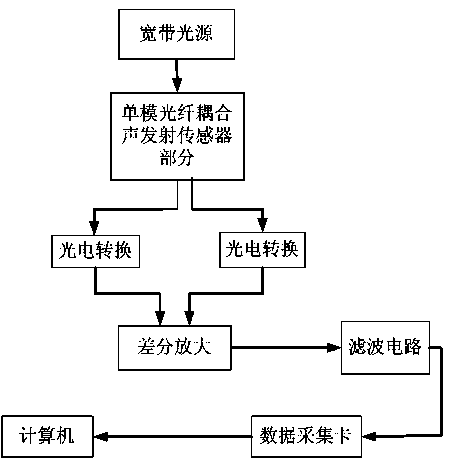
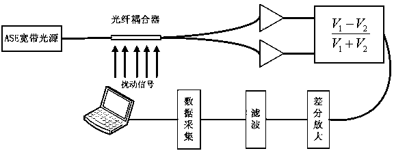
[0023] Such as figure 2 As shown, the present invention provides an acoustic emission sensing system based on a single-mode fiber coupler, including a single-mode fiber-coupled sensor part and a signal processing part, and the single-mode fiber-coupled sensor part includes: an incident optical fiber, an outgoing optical fiber, Single-mode optical fiber coupler and light source; the signal processing part includes: photoelectric conversion circuit, differential amplifier circuit, filter circuit, data acquisition card, computer; wherein the single-mode optical fiber coupler is fastened in the packaging material, and the packaging material and single-mode The fiber couplers are pasted with epoxy resin adhesive; the light emitted by the light source enters the single-mode fiber coupler through two incident fibers, and the two incident lights are output after being ...


PUM

PropertyMeasurementUnit
Center wavelengthaaaaaaaaaa

Abstract

The invention discloses an acoustic emission sensing system based on a single mode fiber coupler. A single mode fiber coupling sensor part comprises incident optical fibers, emergent optical fibers, the single mode fiber coupler and a light source; a signal processing part comprises a photoelectric conversion circuit, a differential amplification circuit, a filter circuit, a data acquisition card and a computer; light emitted by the light source enters the single mode fiber coupler through the two incident optical fibers, and output after coupled in a coupling zone of the single mode fiber coupler; two optical signals are transmitted to the photoelectric conversion circuit by the two emergent optical fibers; the photoelectric conversion circuit converts the optical signals into electrical signals which then enter the data acquisition card sequentially through the differential amplification circuit and the filter circuit; and the data acquisition card performs analog-digital conversion on the acquired signals and then transmits to the computer for analysis processing. According to the system, a complicated mechanical device is not required for sensitization, the influence of outside temperature fluctuation is not required to be considered, and the system has the characteristics of low demodulation cost and high resolution.

Description

technical field [0001] The invention relates to an acoustic emission sensing system based on a single-mode optical fiber coupler, and belongs to the technical field of acoustic emission detection in structural health monitoring. Background technique [0002] Mechanical equipment health monitoring is a relatively new technology developed in the past forty years. It is a comprehensive technology integrating multiple disciplines such as sensors, acoustics, optics, electronics and computer science. Through the measurement and analysis of certain parameters of the equipment, it obtains the trend law of equipment state changes, judges the cause, location and severity of equipment damage, estimates the remaining life of the equipment, and then guides the maintenance and management of the equipment. With the rapid development of this technology, the concept of maintenance and management of mechanical equipment has also undergone tremendous changes, from the past post-accident mainte...

Claims


Application Information

Patent Timeline
IPC IPC(8): G01N29/14
Inventor 朱永凯胡志辉昂洋
Owner NANJING UNIV OF AERONAUTICS & ASTRONAUTICS
Learn More