Lifting mechanism for casting crane

A hoisting mechanism and crane technology, which is applied to cranes, clockwork mechanisms, walking bridge cranes, etc., can solve the problem that it is difficult to meet the technological requirements of steel mills, the left and right limit size of the spreader is increased, and the width of the small frame is large. and other problems, to achieve the effect of reducing the left and right limit size, reducing annealing treatment and overall processing, and reducing the height of the workshop

Inactive Publication Date: 2004-02-18
TAIYUAN HEAVY IND
View PDF0 Cites 7 Cited by
  • Summary
  • Abstract
  • Description
  • Claims
  • Application Information

AI Technical Summary

Problems solved by technology

The disadvantage of the first arrangement is that the reliability is poor. When the coupling between the central reducer and the secondary reducer fails, it is easy to cause the ladle to tilt; To the outermost side of the secondary reducer, the size is larger, which makes the width of the small frame larger, which leads to an increase in the left and right limit dimensions of the spreader, which is difficult to meet the process requirements of the steel plant; the third is the arrangement of the reducer Both the lower box and the reel are above the plane of the trolley frame, and the height of the trolley is relatively large, which increases the project cost
The disadvantage of the second arrangement is that the lower box of the reducer is welded together with the trolley frame
(1) The small frame is required to have sufficient rigidity; (2) The manufacturing process is complex, requiring overall heat treatment and overall processing after welding, otherwise it is difficult to control the manufacturing quality

Method used


Image

  • Lifting mechanism for casting crane
  • Lifting mechanism for casting crane
  • Lifting mechanism for casting crane

Examples


Embodiment Construction

[0019] Typical embodiments of the present invention will be described in detail below in conjunction with the accompanying drawings.

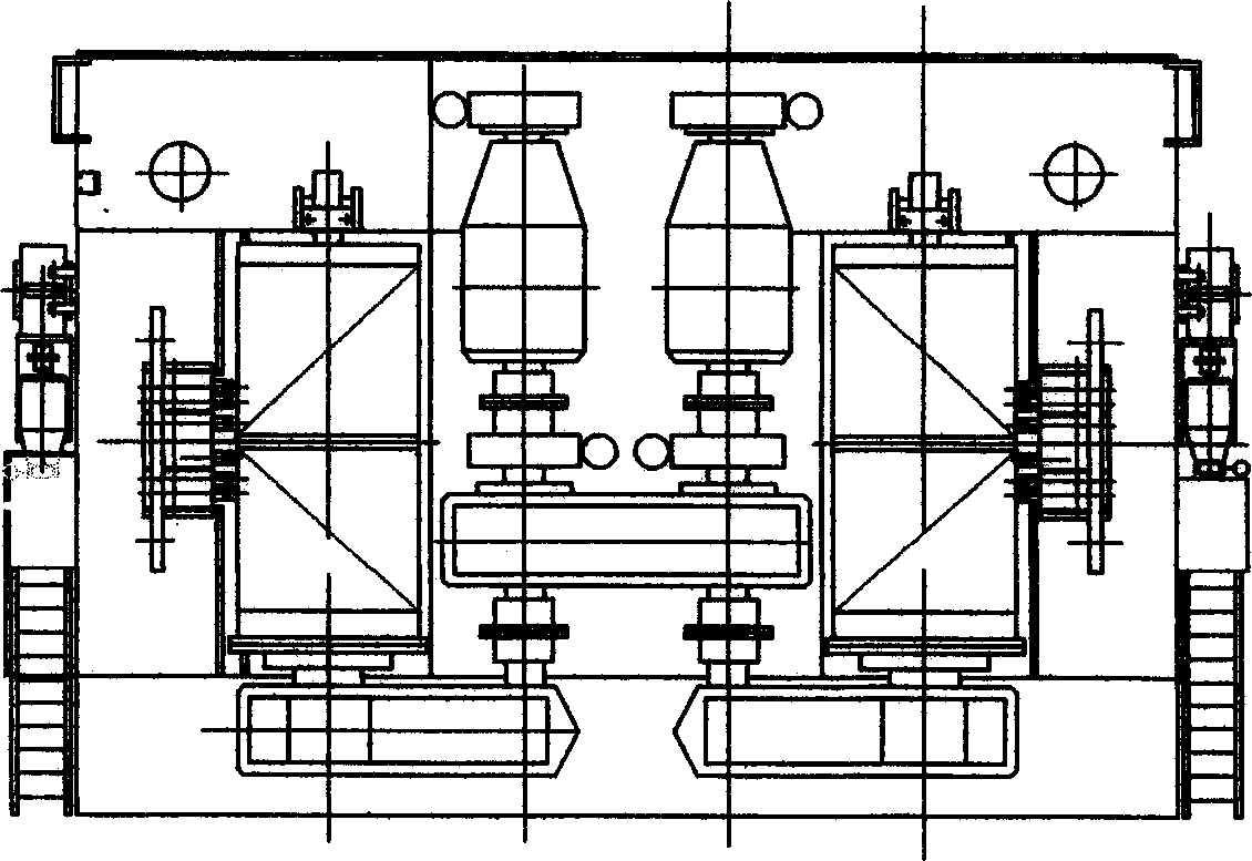
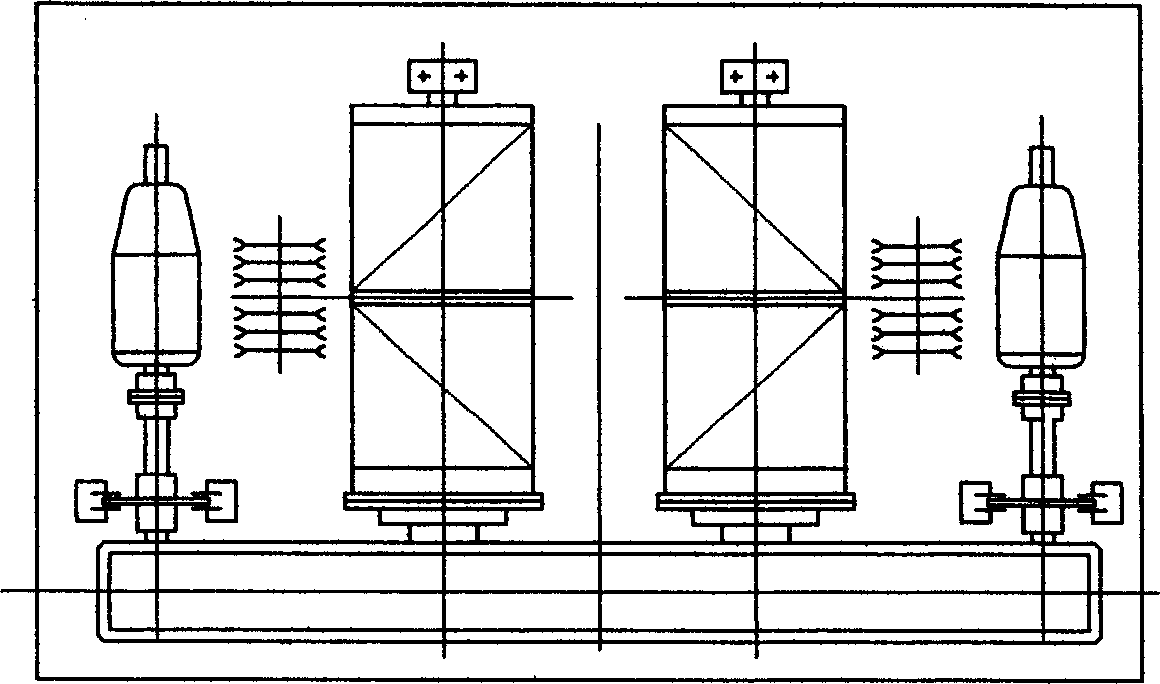
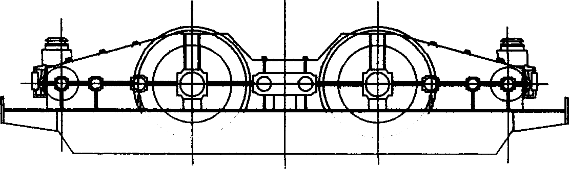
[0020] Figure 4 A hoisting mechanism of a foundry crane is shown. Double drive system consisting of double motors 1, half gear coupling 2, floating shaft 3, half gear coupling with brake disc 5, brake system 4, reducer 9, etc. installed on the trolley frame 10 platform device, the reel device 7, the coupling 8 on the two output shafts of the reel device and the reducer, and the two fixed pulley blocks 6 arranged correspondingly outside the reel device. On each high-speed shaft of the reducer, two disc brakes 4 are respectively installed. The speed reducer is a whole, and a synchronous connection device 11 is arranged between the high-speed gears of the two input shafts. The connecting device can use an idler, and use the idler to connect two sets of driving devices to drive the double reels synchronously; or install a planetary package as a...


PUM


Abstract

A lifting mechanism of foundry hoister is composed of a dual-driving system which is installed on the platform of carriage and consists of two motors, shaft coupling, floating axle, shaft coupling with braking disk, braking system and speed reducer with two input axles and two output axles, dual-winder unit, winder coupling and a group of two static pulleys. Its advantages are small size and highsafety.

Description

technical field [0001] The invention belongs to hoisting and transporting machinery, in particular to a hoisting mechanism of a large and medium casting crane. Background technique [0002] There are two common arrangements for the lifting mechanism of existing large and medium-sized casting cranes: [0003] figure 1 Shown is the hoisting mechanism of a foundry crane designed by the German MAN company and Taiyuan Heavy Industry, which is arranged in the shape of three reducers. Two or four motors drive the two input shafts of the central reducer at the same time. The two output shafts of the reducer respectively drive a high-speed shaft of a secondary reducer through a coupling, and drive a reel on the low-speed shaft of the secondary reducer through a reel coupling. figure 2 , image 3 Shown is the hoisting mechanism of another cast crane with integrated reducer designed by Italian DF company and Taiyuan Heavy Industry, that is, two motors drive the two input shafts of ...

Claims


Application Information

Patent Timeline
IPC IPC(8): B66C11/16B66C17/06B66D1/26
Inventor 顾翠云王首成郝建光宋源高秀芬
Owner TAIYUAN HEAVY IND
Why Eureka
Try Eureka