

Built in gas flow meter and temperature pressure compensation transmission method
A gas flowmeter, built-in technology, applied in the direction of liquid/fluid solid measurement, volume/mass flow generated by detecting the dynamic effect of fluid flow, mechanical effect, etc., can solve the problem of affecting the overall technical performance and appearance quality of the product, reliability Problems such as inability to guarantee safety and accuracy, inconvenient packaging and transportation, etc., achieve the effect of maintenance-free overall technical quality, enhanced anti-interference ability, and convenient transportation
- Summary
- Abstract
- Description
- Claims
- Application Information
AI Technical Summary
Problems solved by technology
Method used
Image

Examples
Embodiment 1
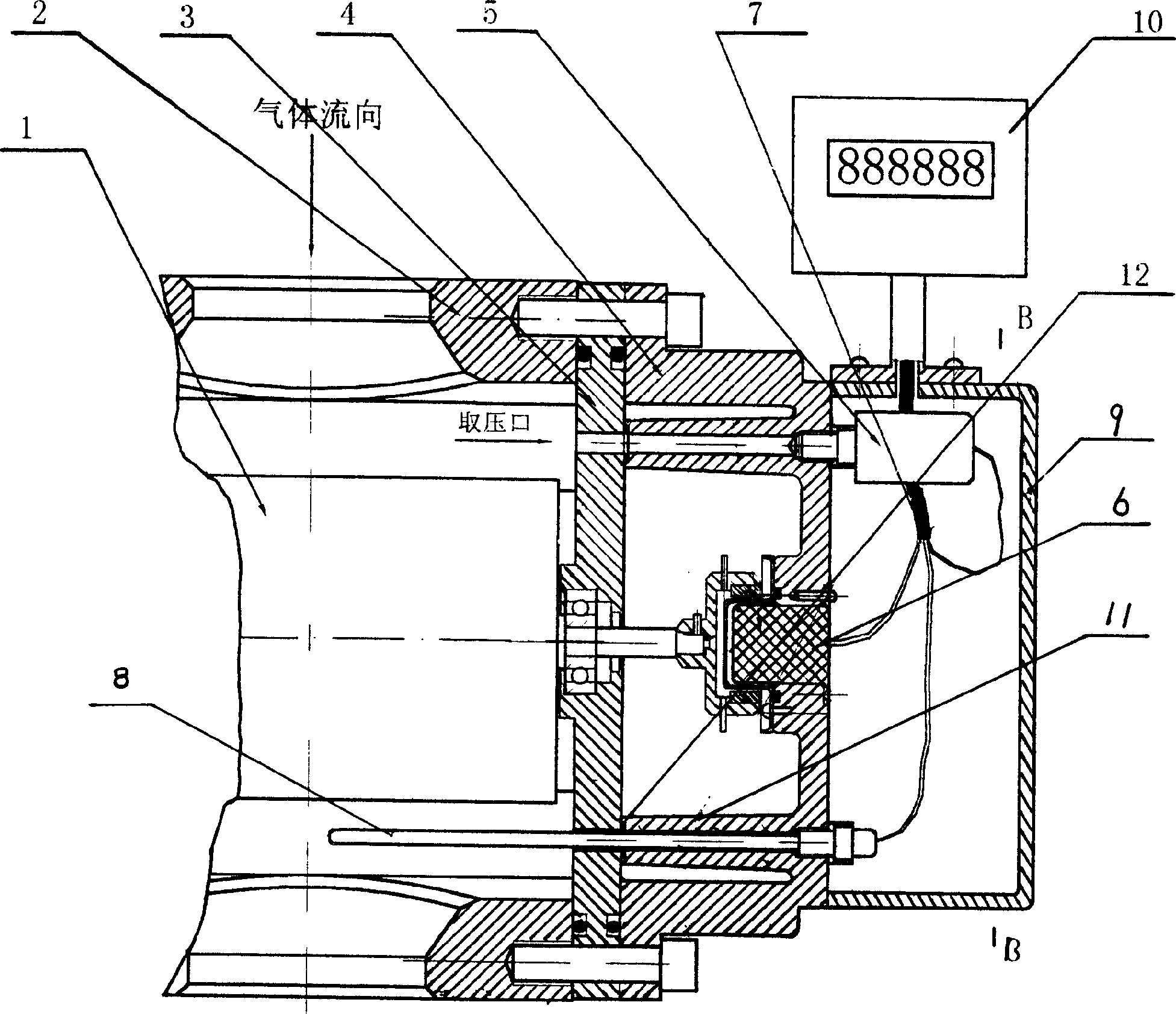
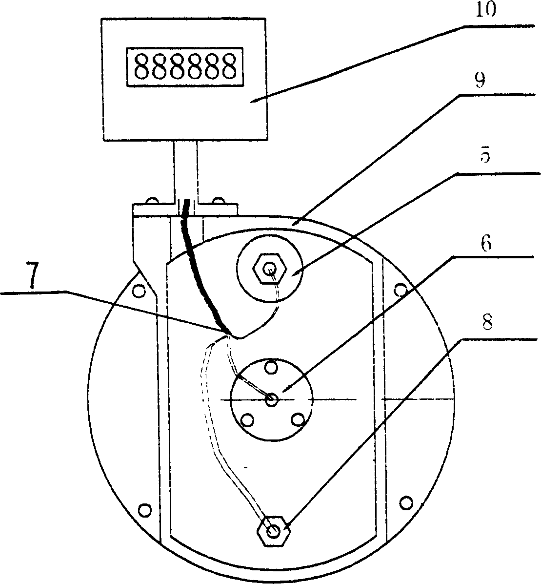
[0011] Embodiment 1: with reference to attached figure 1 and figure 2 . figure 1 and figure 2 Involved in the gas waist wheel flowmeter. The flowmeter includes a fixedly connected flowmeter body 2, a flowmeter partition 3, a flowmeter end cover 4 and a flowmeter cover 9, and the magnetic induction flow signal recorded in the existing patent technology (01253920.1) is removed from the side of the flowmeter end cover. In addition to the output mechanism 6, two passages 11 with O-rings 12 sealing ports are provided at appropriate positions, and the other end of the passage 11 is provided with a threaded sealing port, and pressure sensors (or pressure transmitters) 5 are installed respectively. And temperature sensor (or temperature transmitter) 8, flow signal, pressure signal and temperature signal are sent directly to the microcomputer digital display 10 (also can design For signal remote transmission, processing, reading). A temperature sensor, a pressure signal sampling...
Embodiment 2
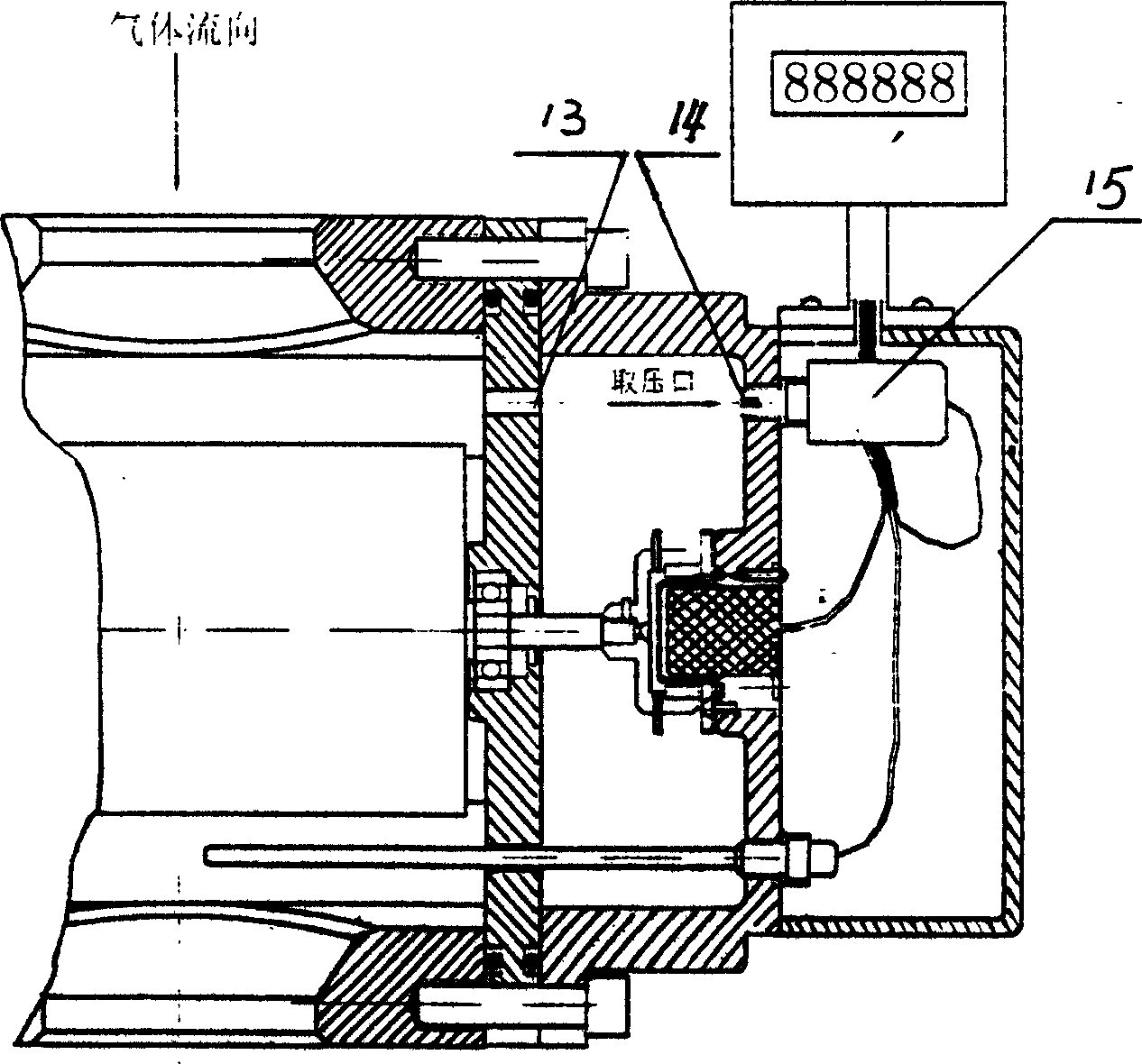
[0013] Embodiment 2: with reference to attached image 3 . Built-in gas flowmeter, the background technology is a gas waist wheel flowmeter or a gas turbine flowmeter, the body is provided with a temperature sensor 8, a pressure signal transmission gas film port 13, a pressure signal sampling port 14 and a pressure signal sampling port matching The pressure sensor 5, the signal transmission line 7 of the pressure sensor and the temperature sensor are located in the body and directly sent to the digital display 10 communicated with the body. The pressure of the gas medium acts on the pressure transmission gas film port 13, and the force deformation of the gas film located on the gas film port directly acts on the incompressible oil, and the oil acts on the sensor located at the sampling port of the pressure sensor to achieve the purpose of pressure sampling .
Embodiment 3
[0014] Embodiment 3: with reference to attached Figure 4 . Mainly used in gas turbines and other gas flow meters. The pressure, temperature sensor (transmitter) and the flow sensor in the embodiment 1 are installed in the cover 9 outside the wall of the flow meter body 2 channels, and the flow sensor receives the flow signal sent by the impeller or other flow signaling mechanism , At the same time, the pressure and temperature sensors measure the pressure and temperature values of the fluid to achieve the same purpose as in Example 1.
PUM
 Abstract
Description
Claims
Application Information