
Ladder type SAW filter and its mfg. method

A manufacturing method and filter technology, applied in the direction of electrical components, impedance networks, etc., can solve the problems of different propagation speeds of surface elastic waves, large differences in propagation speeds of surface elastic waves, and reduction of broadband characteristics of filtering characteristics, so as to reduce propagation The effect of loss

Inactive Publication Date: 2004-03-10
ALPS ALPINE CO LTD
View PDF0 Cites 6 Cited by
  • Summary
  • Abstract
  • Description
  • Claims
  • Application Information

AI Technical Summary

Problems solved by technology

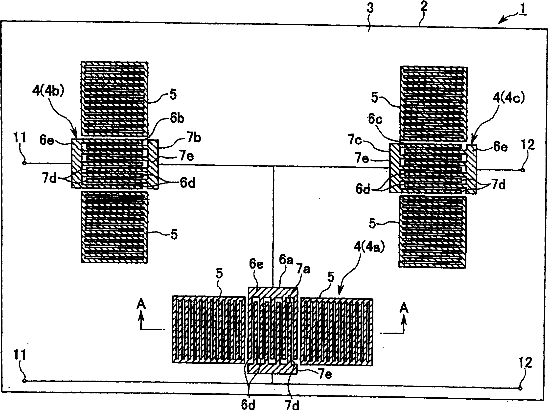
[0004] However, in the ladder-type SAW filter with the above-mentioned structure, if the ZnO thin film is formed only on the R-plane sapphire substrate, the shape of the crystal grains constituting the ZnO thin film is anisotropic. Due to the effect of anisotropy, the propagation speed of the surface elastic wave generated from the IDT on the oscillation side varies depending on the propagation direction
Therefore, depending on the arrangement direction of the IDT, the propagation speed of the surface acoustic wave is greatly different, and the filter characteristics, especially the broadband characteristics, are degraded.

Method used


Image

  • Ladder type SAW filter and its mfg. method
  • Ladder type SAW filter and its mfg. method
  • Ladder type SAW filter and its mfg. method

Examples


Embodiment 1

[0074] (Example 1) "Experimental example 1: Case of A-side sapphire substrate"

[0075] First, a disk-shaped substrate with a diameter of 100 mm exposed on the A surface is prepared in advance, and the substrate is placed in a chamber (chamber) of a sputtering device, and the chamber is temporarily held at 10 -6 ~10 -8 After the vacuum environment of Pa, argon gas was introduced to make the pressure 4-6 Pa.

[0076] Next, with the substrate kept at 350° C., sputtered particles were ejected from a ZnO target body with a diameter of 300 mm by a high-frequency sputtering method and laminated on the substrate. A high frequency of 13.65 MHz and 1.0 kW is applied to the target body. In addition, the incident angle of the sputtered particles to the substrate was set at 90° to the substrate surface. At this time, it is preferable to apply an RF bias voltage of about 10 W also to the substrate side.

[0077] In this way, a piezoelectric layer made of ZnO with a thickness of 0.8 μm wa...

experiment example 2

[0081] Such as Figure 4 As shown, it can be seen that the propagation velocity of the surface elastic wave is in the range of 4700 to 1800 (arbitrary unit) in any direction, and is constant in any direction. "Experimental example 2: Case of R-plane sapphire substrate"

[0082] Prepare a disk-shaped substrate with a diameter of 100 mm that exposes the R surface in advance, and set the substrate in the container of the sputtering device, and temporarily hold the container at 10 -6 ~10 -8 After the vacuum atmosphere of Pa, argon gas was introduced to make the pressure 0.2 to 0.3 Pa.

[0083] Next, with the substrate kept at 300°C, while applying an RF bias voltage with a frequency of 40.68 Hz to the substrate, sputtered particles were shot out from a ZnO target with a diameter of 300 mm by the high-frequency sputtering method, and deposited on the substrate. on the substrate. For the high frequency applied to the target and the substrate, the target frequency was 13.65 Hz, t...


PUM


Abstract

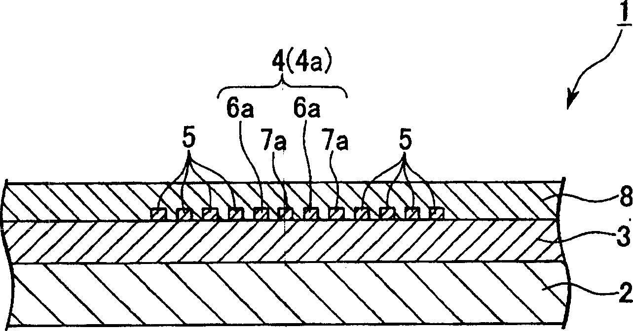
Provided is a ladder SAW filter in which surface acoustic waves are propagated in an isotropic manner, which has no occurrence of different propagation speeds of the surface acoustic waves caused by an arrangement direction of an IDT, and which has almost no deterioration of the broadband characteristics. A piezoelectric layer 3 is formed by gathering a large number of crystal grains in an isotropic shape in a plan view on a substrate 2. A plurality of comb-shaped electrodes 4 having one array direction respectively on the piezoelectric layer 3. The ladder SAW filter 1 is doped in which at least one array direction of the comb-shaped electrode 4a among the comb-shaped electrodes is different from the array directions of the other comb-shaped electrodes 4b, 4c.

Description

technical field [0001] The present invention relates to a ladder-type SAW filter and its manufacturing method, and more particularly to a ladder-type SAW filter suitable for use in mobile communication equipment and the like. Background technique [0002] Generally, an acoustic wave surface element is composed of a piezoelectric layer and a comb-shaped electrode called an IDT for the purpose of electromechanical coupling. A pair of comb-shaped electrodes is provided on the piezoelectric layer to form a resonator, and a SAW filter (surface acoustic wave filter) can be formed by arranging a plurality of the resonators. At this time, one IDT constituting the resonator is arranged perpendicular to the other IDTs to form a ladder-type SAW filter. This ladder-type SAW filter is suitable for use as a wide-band filter because it has a high electromechanical coupling coefficient and the propagation speed of the surface acoustic wave is fast. [0003] Conventionally, there has been ...

Claims


Application Information

Patent Timeline
IPC IPC(8): H03H3/08H03H9/145H03H9/64
Inventor 辻义臣佐佐木真高桥秀幸
Owner ALPS ALPINE CO LTD
Learn More