Magnetic current flowing deformation vibration-damping brake system

A magneto-rheological fluid and brake system technology, applied in the direction of shock absorber, vibration suppression adjustment, non-rotational vibration suppression, etc., can solve the problem of time delay, and there is no synchronous control of damper and brake in the magneto-rheological fluid vibration reduction system Problems such as the poor adaptability of the dynamic system and the damper, etc., to achieve high economic and social benefits

Inactive Publication Date: 2004-03-17
SHANGHAI JIAO TONG UNIV
View PDF0 Cites 8 Cited by
  • Summary
  • Abstract
  • Description
  • Claims
  • Application Information

AI Technical Summary

Problems solved by technology

The passive damper vibration reduction method is to install a simple damper on the braked mechanism or machine. The characteristic parameters of the damper are invariable, so the adaptability of this type of damper is poor; the active damper vibration reduction requires Establish a feedback mechanism. When the structure to be braked changes, the sensor will feed back the information to the control system. After processing, the control system will pass the processing instructions to the damper to make the damper generate corresponding damping force. Active damper control algorithm Complicated and poor controller stability, and there is a problem of time delay
[0006] In the prior art, there is no magneto-rheological fluid damping braking system for synchronous control of the damper and the brake

Method used


Image

  • Magnetic current flowing deformation vibration-damping brake system
  • Magnetic current flowing deformation vibration-damping brake system

Examples


Embodiment Construction

[0015] The specific implementation of the present invention will be further described below in conjunction with the accompanying drawings.

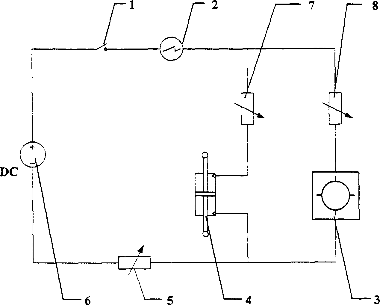
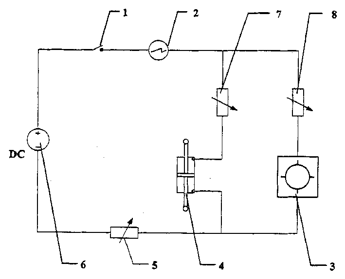
[0016] Such as figure 1 As shown, the present invention mainly includes: brake switch 1, ammeter 2, rotary magneto-rheological fluid brake 3, direct-acting magnetorheological fluid damper 4, variable resistors 5, 7, 8, and DC power supply 6. The rotary magneto-rheological fluid brake 3 and the direct-acting magnetorheological fluid damper 4 are respectively connected in series with the variable resistors 7 and 8 to form a parallel circuit; They are respectively connected in series at both ends of the parallel circuit composed of the magneto-rheological fluid brake 3 and the magneto-rheological fluid damper 4; and then connected in series with the DC power supply 6 to form a magnetorheological fluid damping braking system.

[0017] During application, the two ends of the rotating shaft of the rotary magneto-rheological fluid brake 3, the ...


PUM


Abstract

A magnetic current flowing deformation vibration-damping brake system, mainly comprises a brake switch, a current meter, a rotary magnetic current flowing deforming brake, a straight movement magnetic current flowing deforming brake, a variable resistance and a DC power supply, wherein the rotary magnetic current flowing deforming brake and the straight movement magnetic current flowing deformingbrake are connected in series to the variable resistor to form a parallel circuit, and are connected in series to the DC power supply, the brake switch, the current meter, and the variable resistor to form the magnetic current flowing deformation vibration-damping brake system, which can effectively change the magnitude of the damping moment and damping force provided by the brake and the dampingdevice, achieving a simultaneous vibration-damping braking action for the brake device or machine.

Description

technical field [0001] The invention relates to a damping braking system, in particular to a magneto-rheological fluid damping braking system which realizes synchronous control of a damper and a brake through a brake switch, and belongs to the technical field of engineering vibration. Background technique [0002] Magnetorheological fluid is composed of base fluid, magnetic material suspended in base fluid and stabilizer, and has the characteristics of magnetic material and liquid fluidity. Under the action of an external magnetic field, the rheological properties of magnetorheological fluid can change rapidly, and the rheological properties change with the change of the external magnetic field intensity. The change of the apparent viscosity of the magnetorheological fluid is continuous, reversible, rapid and easy to control, that is, the apparent viscosity of the magnetorheological fluid has the characteristics of stepless adjustment, so that the magnetorheological fluid is...

Claims


Application Information

Patent Timeline
Patent Type & Authority Applications(China)
IPC IPC(8): F16F9/53F16F13/30
Inventor 邹剑陈进董广明
Owner SHANGHAI JIAO TONG UNIV
Why Eureka
Try Eureka