
Method and apparatus for calibration of laser three-dimensional measuring appliance

A laser three-dimensional measuring device technology, applied in the direction of measuring devices, optical devices, instruments, etc., can solve the problems of unfavorable weight, large laser measuring head correction, unsuitable laser measuring head, large volume, etc., to overcome optical distortion, The effect of reducing calculation time and improving measurement accuracy

Inactive Publication Date: 2004-03-17
IND TECH RES INST
View PDF1 Cites 16 Cited by
  • Summary
  • Abstract
  • Description
  • Claims
  • Application Information

AI Technical Summary

Problems solved by technology

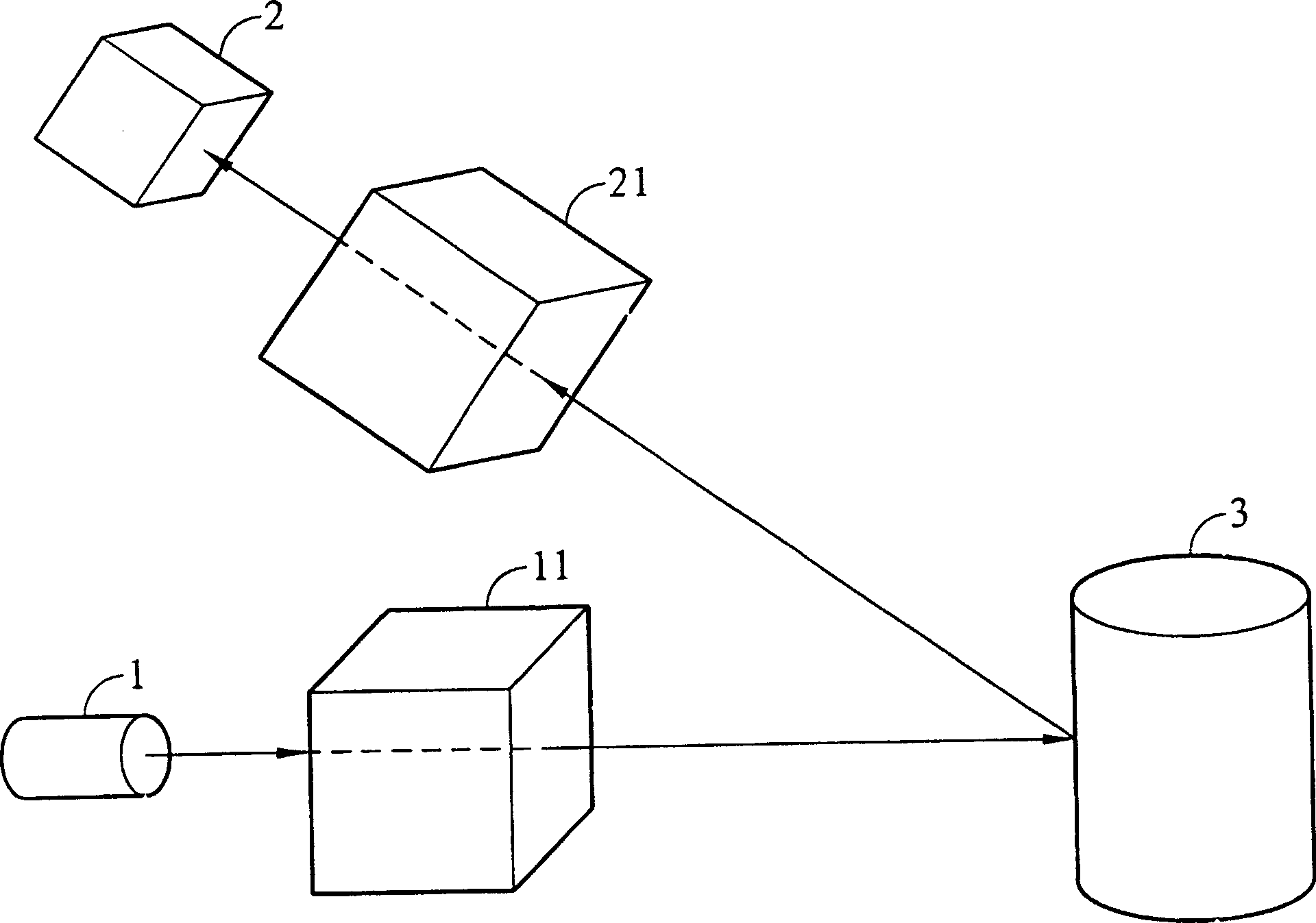
[0008] However, the above calibration method and device are designed for the calibration of laser measuring heads that generally use single-point scanning, but are not applicable to laser measuring heads such as the present invention or having single-line scanning characteristics
And because the laser line in this case is obliquely projected onto the plane on the block, the reflection conditions of the plane (such as the smoothness of the surface) will easily affect its correction accuracy, so this method still needs to be properly corrected. At the same time, the above-mentioned oblique In general, the laser measuring head needs to be suspended and placed in the projection mode, which will not be conducive to the calibration of some heavy and large laser measuring heads, such as body scanners (Body Scanner), etc.
[0009] In addition, as in the aforementioned U.S. Patent No. 4,825,308, the calibration device must use a very high-precision XYZ linear platform and a square gauge, especially the positioning accuracy and verticality of the X, Y, and Z axes must be very high, so the equipment volume Larger and more expensive

Method used


Image

  • Method and apparatus for calibration of laser three-dimensional measuring appliance
  • Method and apparatus for calibration of laser three-dimensional measuring appliance
  • Method and apparatus for calibration of laser three-dimensional measuring appliance

Examples


Embodiment Construction

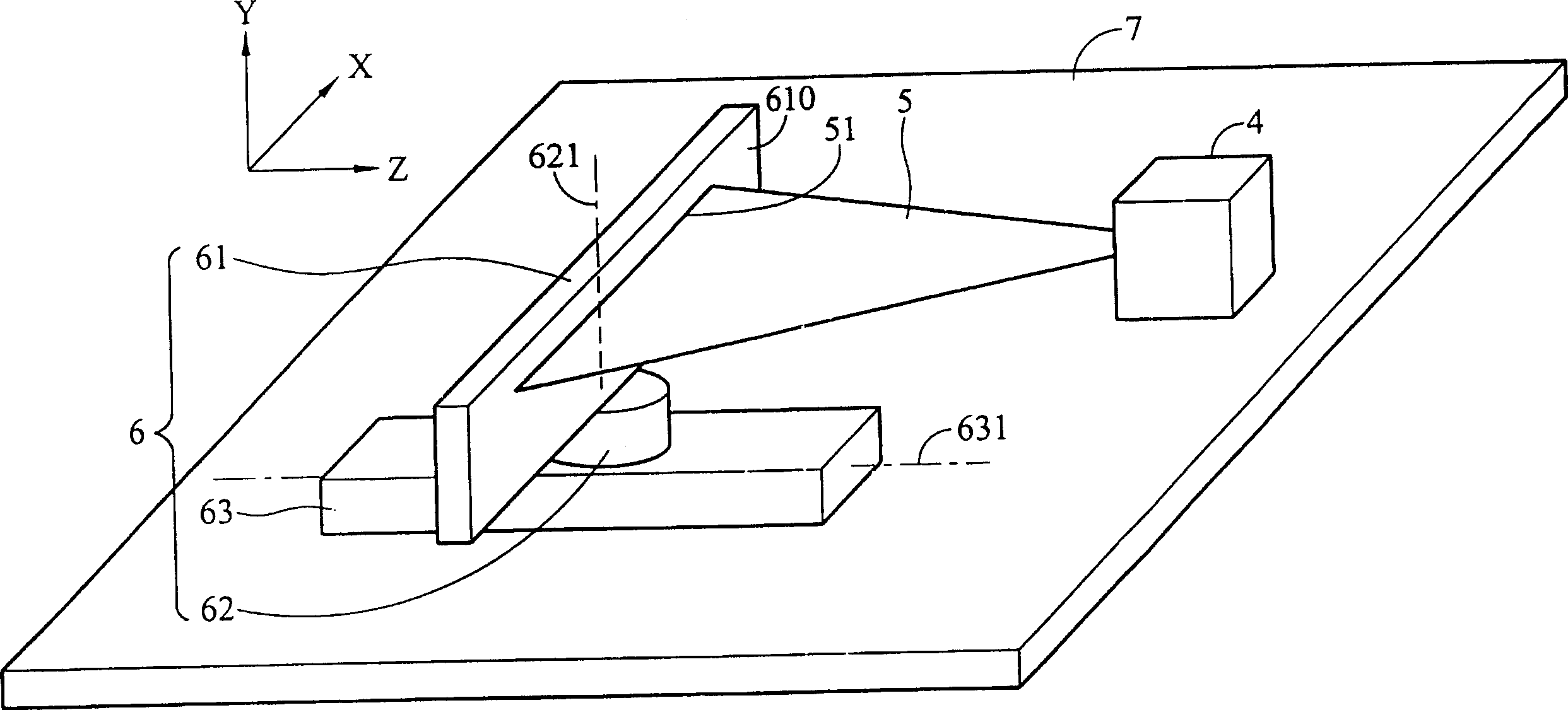
[0038] like figure 2 As shown, the figure shows a schematic diagram of the laser three-dimensional measuring device calibration device of the present invention, wherein the present invention mainly includes a laser measuring head 4 , a laser plane 5 , a calibration mechanism 6 , and a reference plane 7 .

[0039] As shown in the figure, this embodiment defines an X-axis, a Y-axis and a Z-axis of a Cartesian coordinate system in a three-dimensional space. The laser measuring head 4 can emit a laser plane 5, and the laser measuring head 4 and the calibration mechanism 6 are stably placed on the reference plane 7, and the reference plane 7 is parallel to the XZ plane as shown in the figure. .

[0040] In addition, the laser measuring head 4 has the function of sensing light, and can thereby generate a two-dimensional digital image 8 (such as Figure 3B shown); in general, the laser measuring head 4 can be connected to a computer (not shown) for storing digital image data and c...


PUM


Abstract

The invention discloses a method and apparatus for calibration of laser three-dimensional measuring appliance, wherein the apparatus includes a base plane and a laser gauge pin arranged on base planeand able to set out a lasing plane, an aligning gear arranged on base plane, which includes a surface gauge, an adjusting plane is arranged on the surface gauge, and the correction method is, the laser gauge pin sending laser plane, projecting on the plane gauge, then the laser gauge pin can sense the reflected ray, and obtain a two-dimensional digital image.

Description

technical field [0001] The present invention relates to a calibration method and device for a three-dimensional optical measuring system, in particular to a method and device for calibrating a laser three-dimensional measuring device. Background technique [0002] Existing optical triangulation systems have been widely used in various 3D space measurement systems, such as machine vision, automated inspection, or in various manufacturing and assembly processes; however, these 3D measurement systems have advantages and disadvantages. Often depends on the calibration accuracy of the system. Therefore, how to design a set of calibration procedures and methods with simple procedures and high accuracy for the 3D measurement system is indeed an important issue. [0003] Generally, extra expenditure is required to manufacture a calibration instrument for a three-dimensional measurement system, and for a system requiring high precision, the required calibration cost is not only high...

Claims


Application Information

Patent Timeline
Patent Type & Authority Applications(China)
IPC IPC(8): G01B11/00G01B11/26
Inventor 罗文秀林明慧
Owner IND TECH RES INST
Learn More