I-Wheel curling formation process

A forming process and a technology of the I-shaped wheel, which is applied in the field of curling forming process, can solve the problems of labor and material, low yield and low work efficiency.

Inactive Publication Date: 2004-04-07
卢惠林
View PDF0 Cites 20 Cited by
  • Summary
  • Abstract
  • Description
  • Claims
  • Application Information

AI Technical Summary

Problems solved by technology

[0002] The side plate of the I-shaped wheel used for winding is made of steel plate. In order to reduce weight and improve strength and rigidity, round pipes are usually welded around it as a reinforcing edge. This welding method is not only labor-intensive and material-intensive, but also Deformation affects performanc

Method used


Image

  • I-Wheel curling formation process
  • I-Wheel curling formation process
  • I-Wheel curling formation process

Examples


Embodiment Construction

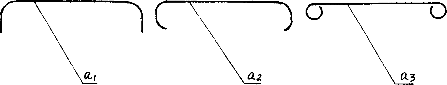
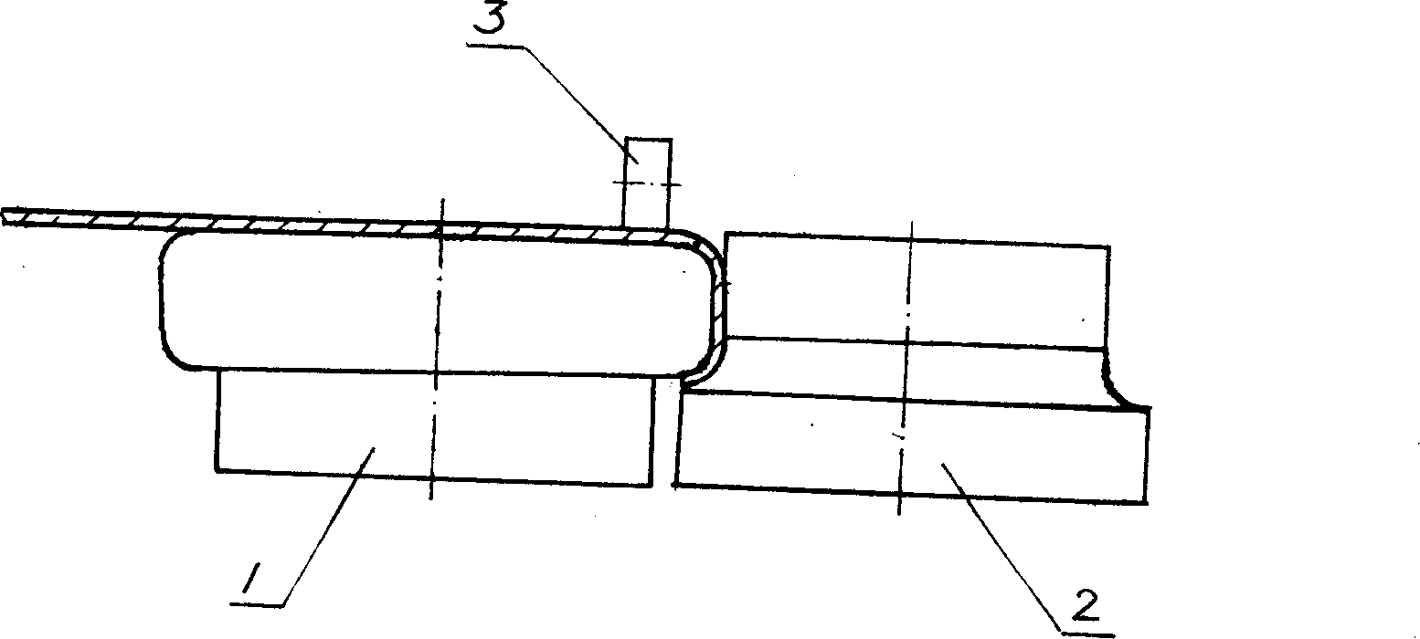
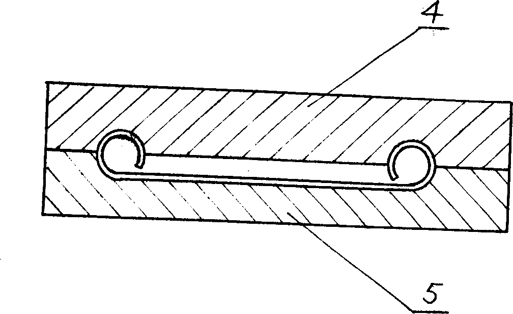
[0010] The side plate of the I-shaped wheel is obtained by three steps of bending, rolling and forming from a circular steel plate as follows: figure 1 in, a 1 、a 2 、a 3 cross-sectional shape. Step 1 is carried out on a punching machine using a bending die. Step 2 is completed by using a special rolling die connected with the transmission mechanism. In the rolling die, the inner R die 1 is the driving wheel driven by the motor, the outer R die 2 is the driven wheel that can be used for radial feed, and the arc R on the inner and outer R dies 1 , R 2 Complies with R 2 = R 1 +δ, δ is the thickness of the workpiece. When working, the workpiece a is set on the inner R die 1, the top surface is exerted vertical pressure by the pressing wheel 3, and the side is exerted horizontal pressure by the outer R die 2, and the vertical pressure and the horizontal pressure are provided by the hydraulic cylinder. Step 3 is carried out on a hydraulic press using a forming die, which in...


PUM


Abstract

The I-wheel curling formation process includes three steps of bending, rolling and shaping to form right-angled, arced or tubular hems in the edges of circular steel plate. The rolling step is completed with special rolling mold with transmission mechanism , the rolling mold includes inner driving wheel and radially feeding inner driven wheel, and the vertical pressure and the horizontal pressure of the workpiece applied on the driving wheel are provided by the hydraulic oil cylinder. Compared with available welding and extruding formation process, the technological process of the present invention has significant progress.

Description

technical field [0001] The invention relates to a curling forming process of a steel plate, in particular to a curling forming process of a side plate of an I-shaped wheel by using a special mold. Background technique [0002] The side plate of the I-shaped wheel used for winding is made of steel plate. In order to reduce weight and improve strength and rigidity, round pipes are usually welded around it as a reinforcing edge. This welding method is not only labor-intensive and material-intensive, but also Deformation affects performance. At present, it has been proposed to use tubular curling type I-shaped wheel side panels, which has made significant progress, but the processing method is not yet perfect. Generally, it is divided into 4 to 5 steps of extrusion molding step by step. The disadvantage is that the work efficiency is low and the yield is also low. Contents of the invention [0003] The object of the present invention is to overcome the disadvantages of the pr...

Claims


Application Information

Patent Timeline
IPC IPC(8): B21D19/04B21D19/12
Inventor 卢惠林
Owner 卢惠林
Why Eureka
Try Eureka