

Washing machines
A washing machine and forced circulation technology, applied in the field of washing machines, can solve the problems of difficulty in promoting the dissolution of detergent/powder, less water, difficult cleaning effect, etc., and achieve the effects of improving cleaning performance, promoting dissolution, and improving circulation efficiency
- Summary
- Abstract
- Description
- Claims
- Application Information
AI Technical Summary
Problems solved by technology
Method used
Image

Examples
Embodiment 1
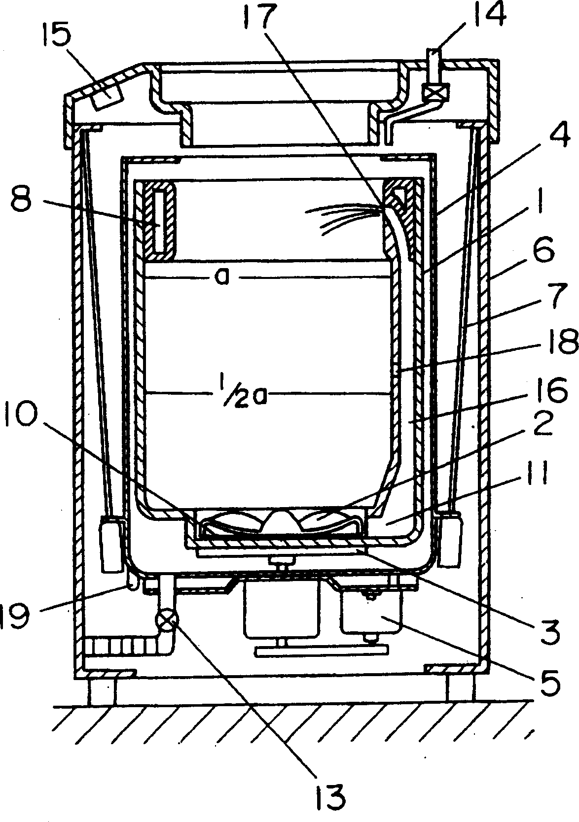
[0024] Such as figure 1 As shown in the figure, the drain valve 13 is used to discharge the washing water in the outer tub 4 to the outside, and the water inlet valve 14 is used to supply water to the washing and dehydrating tub 1. The control device 15 controls the operation of the motor 5, the drain valve 13, the water inlet valve 14, etc., and completes a series of operations such as washing, rinsing, and dehydrating in sequence.
[0025] On the side surface of the washing and dehydrating tub 1, a forced circulation water passage 16 is provided from the pump chamber 11 formed on the periphery of the lower blade 10 of the pulsator 2 to the vicinity of the fluid balance ring 8. The forced circulation water path 16 is provided with a first spray port 17 for spraying washing water from the upper part of the washing and dehydrating tub 1 under the action of the pump water of the lower blade 10 of the pulsator 2, and a first spray port 17 located at the first spray water. The second...
Embodiment 2
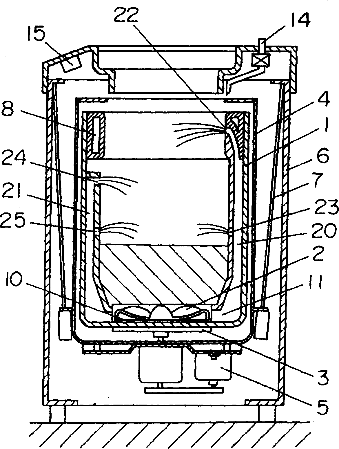
[0032] Such as image 3 As shown in the figure, a first forced circulation water passage 20 and a second forced circulation water passage 21 are formed in the washing and dehydration tub 1, and they are respectively arranged at opposite positions in the washing and dehydration tub 1. The first forced circulation water channel 20 is provided with a first water jet 22, and a second water jet 23 is provided at a height below the first water jet 22. Similarly, the second forced circulation water path 21 is also provided with a first water nozzle 24 and a second water nozzle 25 located at a height below the first water nozzle 24, and the first water nozzle 24 is provided in The first water jet 22 in the first forced circulation water channel 20 is located at a low position. The other constitutions are the same as those of the first embodiment, and we label them with the same symbols and omit their descriptions.
[0033] The operation of the above configuration is described below. In the...
Embodiment 3
[0038] Such as Figure 4 As shown in the figure, a first forced circulation water passage 26 and a second forced circulation water passage 27 are formed in the washing and dehydration tub 1 and are respectively arranged at opposite positions in the washing and dehydration tub 1. The first forced circulation water channel 26 is provided with a first water jet 28 and a second water jet 29 whose height is below the first water jet 28. Similarly, the second forced circulation water path 27 is also provided with a first water jet 30 and a second water jet 31 whose height is below the first water jet 30.
[0039] In addition, the first water jet 28 of the first forced circulation water channel 26 is at a different height from the first water jet 30 of the second forced circulation water channel 27. In addition, the heights of the second water jets 29 and 31 are also set to Different from each other.
[0040] The height of each water jet of each forced circulation waterway is set at a po...
PUM
 Abstract
Description
Claims
Application Information