Mixer for warming radiating earth bed
A mixer and ground bed technology, applied in the field of hot water central heating system, can solve the problems of large heat energy consumption and unfavorable service life of heating pipelines
- Summary
- Abstract
- Description
- Claims
- Application Information
AI Technical Summary
Problems solved by technology
Method used
Image

Examples
Embodiment 1
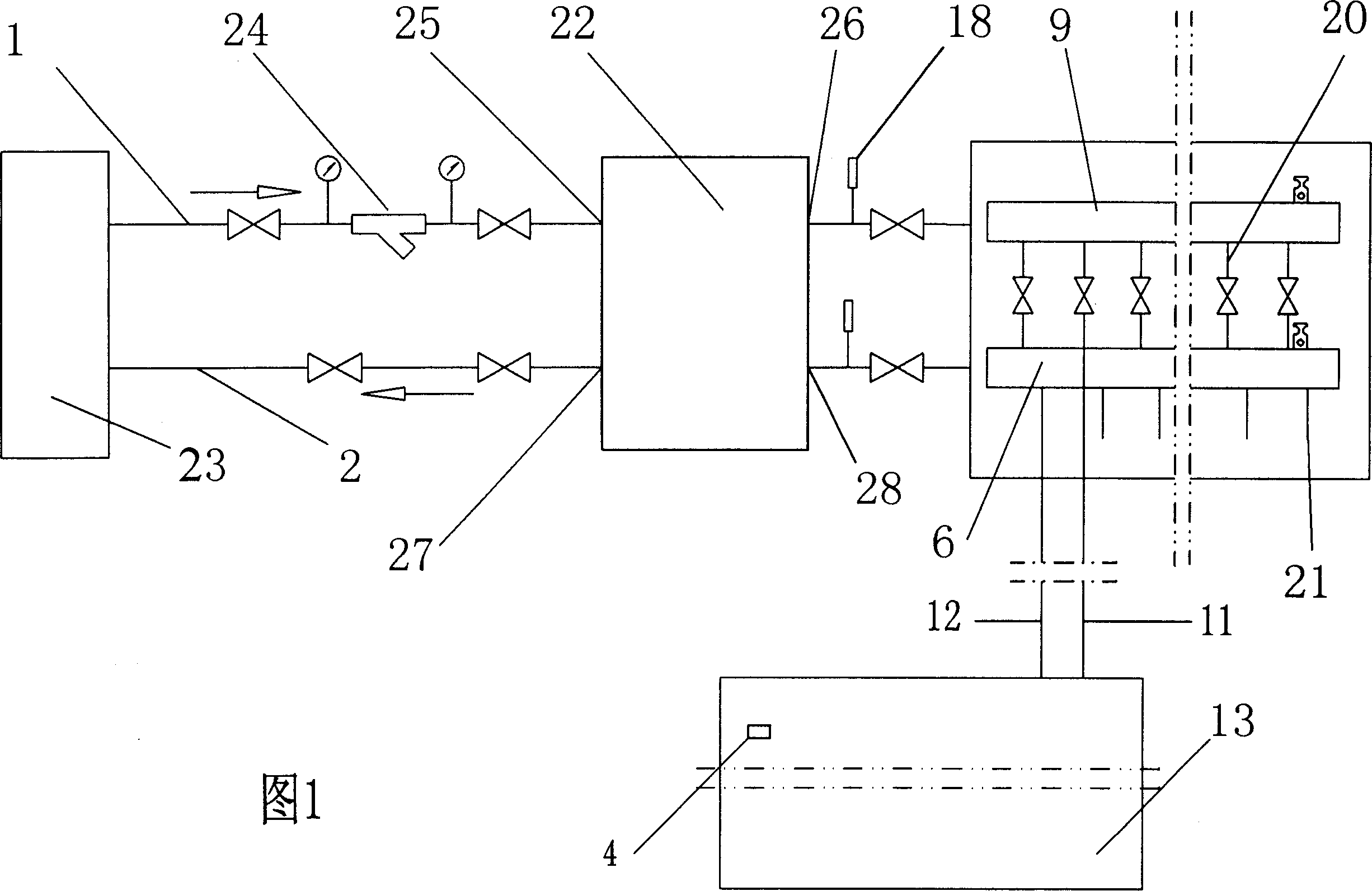
[0063] One end of the main water inlet pipe (1) is connected with the output port of the heater (23), the other end of the main water inlet pipe (1) is connected with one end of the filter (24), and the other end of the filter (24) It is connected with the mixed-flow water inlet port (25) of the flow mixer (22), and the mixed-flow water inlet outlet (26) of the flow mixer (22) is connected with the input port of the thermometer (4) and the water distributor (13). The water delivery port (20) of the water device (9) is connected with the water inlet pipe (11) of the heating place (13), and an exhaust valve (10) is arranged on the water separator (9).
[0064] One end of the main return pipe (2) is connected to the return water input port of the heater (23), and the other end of the main return pipe (2) is connected to the mixed flow return water output port (27) of the mixer (22). The mixed flow return water inlet (28) of (22) is connected with the output port of thermometer (4...
Embodiment 2
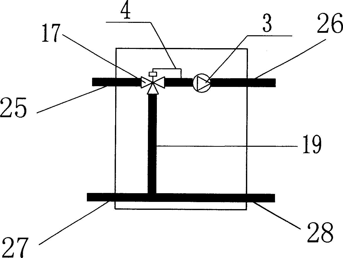
[0068] The mixed flow inlet port (25) of the flow mixer (22) is connected with the water inlet of the electric three-way valve (17), and the water outlet of the electric three-way valve (17) is connected with the water inlet of the circulation pump (3). The temperature sensor (4) of the electric three-way valve (17) is connected with the water inlet of the circulation pump (3), the water outlet of the circulation pump (26) is connected with the mixed flow water inlet outlet (26), and the return pipe (19 ) is connected with the return port of the electric three-way valve (17). The mixed flow return water outlet (27) is connected with the other end of the return pipe (19) and the mixed flow return water inlet (28), and the mixed flow return water inlet (28) is connected with the water outlet of the water collector (6) .
[0069] Use the temperature sensor (4) of the electric three-way valve (17) to measure the water inlet temperature of the water inlet of the circulating pump (...
Embodiment 3
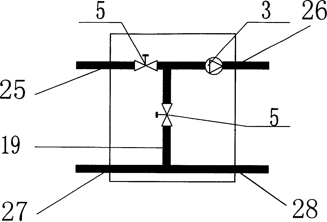
[0071] The mixed flow water inlet port (25) of the flow mixer (22) is connected with the water inlet of the temperature sensing valve (16), and the water outlet of the temperature sensing valve (16) is connected with the water inlet of the circulation pump (3) and the mixed cut-off valve (8) The water outlets are connected, and the temperature sensor (4) of the temperature sensing valve (16) is connected with the water inlet of the circulating pump (3). The water outlet of the circulation pump (3) is connected with the mixed flow water inlet outlet (26), and one end of the return pipe (19) is connected with the water inlet of the mixed shut-off valve (8). The mixed flow return water outlet (27) of the flow mixer (22) is connected with the other end of the return pipe (19) and the mixed flow return water inlet (28).
[0072] Measure the temperature of the heating medium at the water inlet of the circulating pump (3) by the temperature sensor (4) of the temperature sensing valve...
PUM
 Abstract
Description
Claims
Application Information
 - R&D
- Intellectual Property
- Life Sciences
- Materials
- Tech Scout
- Unparalleled Data Quality
- Higher Quality Content
- 60% Fewer Hallucinations
Browse by: Latest US Patents, China's latest patents, Technical Efficacy Thesaurus, Application Domain, Technology Topic, Popular Technical Reports.
© 2025 PatSnap. All rights reserved.Legal|Privacy policy|Modern Slavery Act Transparency Statement|Sitemap|About US| Contact US: help@patsnap.com