Bin level testing method

A technology of material level detection and detection device, which is applied in the direction of measuring device, liquid/fluid solid measurement, liquid level indicator for physical variable measurement, etc., can solve the problem that the sensor cannot be selected, the signal accuracy and stability are difficult to guarantee, and the price of the sensor Advanced problems, to achieve the effect of wide application, high reliability, and simple device structure

Inactive Publication Date: 2004-04-21
TIANJIN CEMENT IND DESIGN & RES INST
View PDF0 Cites 10 Cited by
  • Summary
  • Abstract
  • Description
  • Claims
  • Application Information

AI Technical Summary

Problems solved by technology

The above-mentioned sensors are generally expensive, and are greatly affected by the environment and the physical state of the medium when used, and the accuracy and stability of the signal are difficult to guarantee
Unable to select an available sensor in some cases

Method used


Image

  • Bin level testing method
  • Bin level testing method
  • Bin level testing method

Examples


Embodiment Construction

[0020] Brief description of structure and working principle

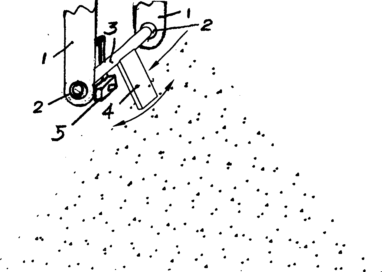
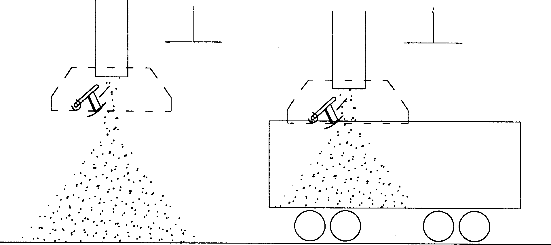
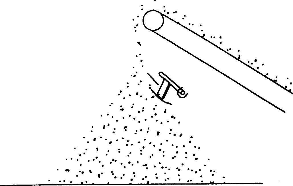
[0021] figure 1 In the material level detection method shown, a freely rotating or swinging object is installed at the position where the material level signal needs to be obtained. The material will flow downward along the angle of repose, and the material that has contacted the device object will push the device object to generate displacement when it flows downward, and the displacement is the signal that the material reaches the position. The displacement signal can be converted into an electrical switch signal through a proximity switch or a travel switch.

[0022] The object that can rotate freely and swing is that a bearing 2 is arranged on a fixed frame 1, and the bearing is equipped with a shaft 3, and a swing plate 4 is installed on the shaft; a displacement signal detection device 5 is installed near the swing plate on the fixed frame. The displacement signal detection device may be a travel switch. Th...


PUM


Abstract

In the method, an object which can rotate and swing freely is set at position where the material level signal is required. The object is pushed to have a displacement by down wards flowing material when the object is contacted with material which is piled up to the above said position since material at pile top flows down wards along the angle of repose in course of material continuous piling up. The displacement represents signal that the material reaches the position and the displacement is converted to be electrical switching signal by displacement signal detection device set near the object.

Description

technical field [0001] The invention belongs to an object position detection method, in particular to a material level detection method. Background technique [0002] During the work of conveying and accumulating solid powder and granular materials, when the materials are accumulated to a certain height or close to the position of the conveying and discharging device, it is necessary to obtain a signal of the height of the material level for controlling the stop of the discharge, or moving The discharge device avoids material blockage. At present, this signal can be obtained by capacitive, inductive, radar, ultrasonic, tuning fork and other sensors. The above-mentioned sensors are generally expensive, and are greatly affected by the environment and the physical state of the medium during use, so it is difficult to guarantee the accuracy and stability of the signal. In some cases an available sensor cannot be selected. Contents of the invention [0003] The technical pro...

Claims


Application Information

Patent Timeline
Patent Type & Authority Applications(China)
IPC IPC(8): G01F23/00G01F23/22
Inventor 季永利
Owner TIANJIN CEMENT IND DESIGN & RES INST
Why Eureka
Try Eureka