Image processing apparatus and ultrasonic wave diagnosis apparatus

An image processing equipment, ultrasonic technology, applied in the direction of acoustic wave diagnosis, infrasound wave diagnosis, image data processing, etc., can solve the problems of inability to understand the internal structure, inconvenient inspection, troublesome tasks and so on

Inactive Publication Date: 2004-05-05
KK TOSHIBA
View PDF1 Cites 35 Cited by
  • Summary
  • Abstract
  • Description
  • Claims
  • Application Information

AI Technical Summary

Problems solved by technology

[0011] However, for clipping or MPR image positioning, the body needs to be fine-tuned with the mouse while rotating the body, so if the three-dimensional image is displayed in real time and changes in it, such as blood flow, are checked, the technician must hold the ultrasound probe in the 3D in-body shooting is performed sequentially, and complex operations such as clipping operations are performed simultaneously for volume rendering, so this setup is not practical from the standpoint of operability
[0012] In addition, for volume rendering images, there is also a problem that the interna

Method used


Image

  • Image processing apparatus and ultrasonic wave diagnosis apparatus
  • Image processing apparatus and ultrasonic wave diagnosis apparatus
  • Image processing apparatus and ultrasonic wave diagnosis apparatus

Examples


no. 1 example

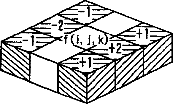
[0058] First, in the first embodiment, the face extraction (face extraction) processing is the feature of this embodiment, and the face extraction processing (high frequency band enhancement filtering processing) is performed on the equal voxel volume to generate a volume with enhanced face components, and then the Each sample value is subjected to volume rendering processing, thereby displaying a volume rendering image with enhanced area components.

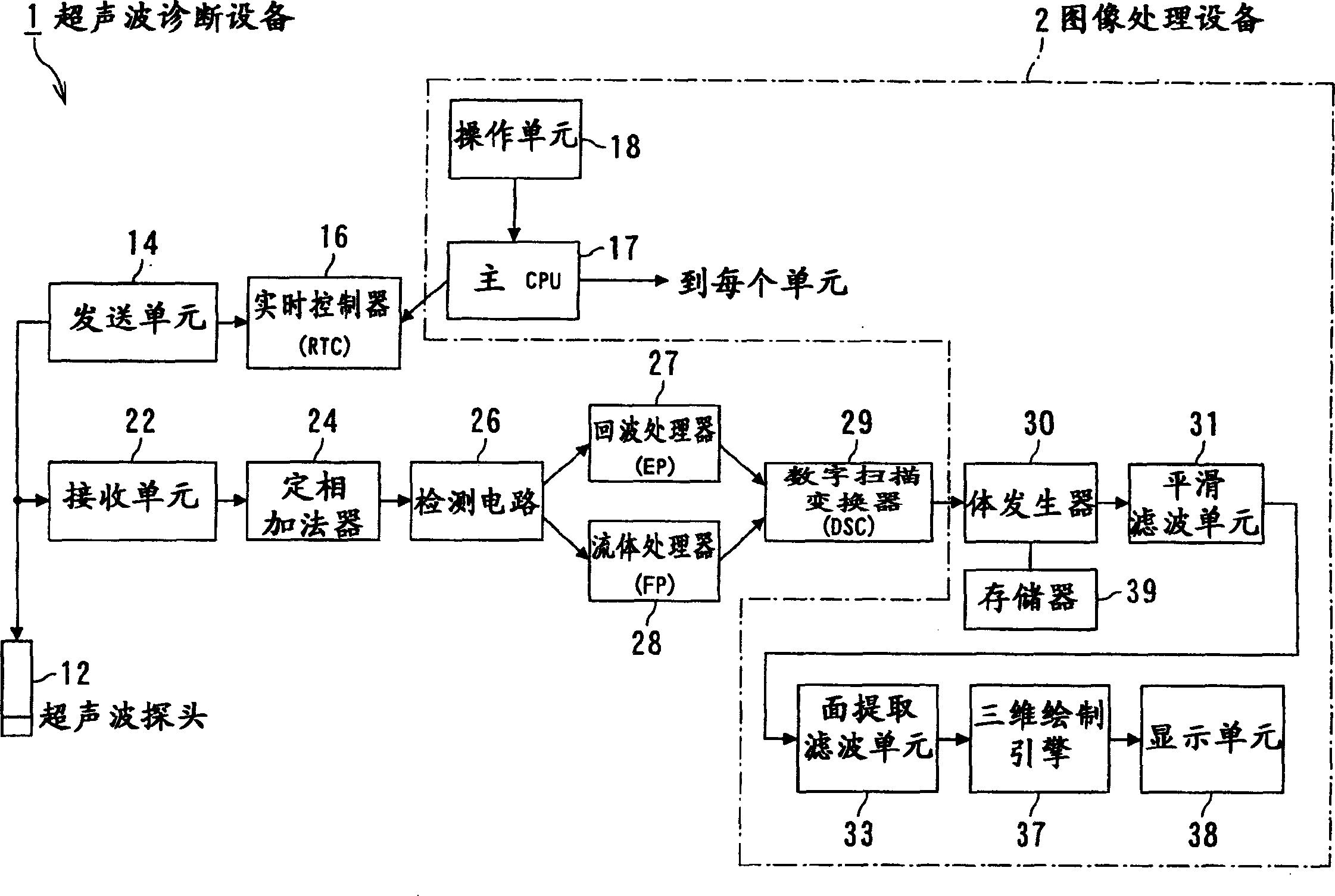
[0059] Before describing these features, refer to figure 1 The general principle configuration of the ultrasonic diagnostic equipment serving as its basis is explained. figure 1 is a block diagram showing a configuration example of the ultrasonic diagnostic apparatus according to the present embodiment.

[0060] (Configuration of ultrasonic diagnostic equipment)

[0061] Such as figure 1 As shown, the ultrasonic diagnostic device according to this embodiment includes: an ultrasonic probe 12 for sending and receiving ultrasoni...

no. 2 example

[0170] Next, refer to Figure 8 A second embodiment according to the present invention will be described. Its configuration is substantially the same as that in the first embodiment, so a description of its configuration will be omitted below. Components generally having the same function and configuration are denoted by the same reference numerals as those in the first embodiment, and they will not be described in detail unless necessary, so basically only different parts will be described. Figure 8 is a functional block diagram showing a configuration example of the ultrasonic diagnostic apparatus according to the present embodiment.

[0171] For the first embodiment, the smoothing filter is configured as a three-dimensional filter using a predetermined number of surrounding samples, meanwhile, for this embodiment, the smoothing filter is decomposed into X, Y, and Z directions respectively, and is performed using a two-dimensional filter deal with.

[0172] Specifically,...

no. 3 example

[0186] Next, refer to Figure 9 A third embodiment according to the present invention will be described. Its configuration is substantially the same as that in the above-described embodiment, so description of its configuration will be omitted below. Components generally having the same functions and configurations are denoted by the same reference numerals as in the above-described embodiments, and they will not be described in detail unless necessary, so basically only different parts will be described. Figure 9 is a functional block diagram showing a configuration example of the ultrasonic diagnostic apparatus according to the present embodiment.

[0187] While the above-described embodiments have described the configuration in which face extraction filtering is performed on voxel volumes, the present embodiment discloses a configuration in which face extraction filtering is performed on radially extended volume data.

[0188] (Configuration of ultrasonic diagnostic equi...


PUM


Abstract

An acquired volume data from a subject, which is allocated in points constituting three-dimensional space and forming a group of data representing a physical property of the subject, is recorded in a recording means, a characteristic quantity computed from values of the physical property held by the volume data at each point is extracted by a characteristic quantity extracting means, and three-dimensional image is generated by providing opacity to the characteristic quantity by three-dimensional image generating means, whichever the volume data is voxel volume data or polar-coordinate ultrasound volume data, so that the internal structure of parenchymatous organs, especially internal blood vessels and cavitary structures can be displayed three dimensionally.

Description

technical field [0001] The present invention relates to an image processing device and an ultrasonic diagnostic device for imaging a three-dimensional body representing physical properties of a medical subject. Background technique [0002] In recent years, at the scene of medical activities such as diagnosis and treatment, such as ultrasonic diagnostic equipment, X-ray CT equipment, X-ray diagnostic equipment, magnetic resonance imaging (MRI) equipment, nuclear medical diagnostic equipment (gamma ray camera) The images produced on medical imaging diagnostic equipment are displayed as three-dimensional images for diagnosis or treatment. In the field of 3D image diagnosis, for example, images are usually obtained by using a volume method, and the 3D images are displayed by performing volume rendering (hereinafter referred to as "VR"), and doctors find diseases by viewing the 3D images. [0003] For example, volume rendering involves slicing images obtained by ultrasonic diag...

Claims


Application Information

Patent Timeline
IPC IPC(8): A61B8/00G01S7/52G01S15/89G06T1/00G06T15/08G06T19/00
CPCG01S15/8988G01S15/8979G01S7/52036A61B8/463G01S7/52034A61B8/483G01S7/52074A61B8/00G01S15/8993G06T15/08
Inventor 橋本敬介
Owner KK TOSHIBA
Why Eureka
Try Eureka