Energy system for watercraft

A watercraft, energy technology, applied in the field of energy systems

Inactive Publication Date: 2004-05-19
SIEMENS AG
View PDF1 Cites 13 Cited by
  • Summary
  • Abstract
  • Description
  • Claims
  • Application Information

AI Technical Summary

Problems solved by technology

[0005] These disadvantages are especially serious when the watercraft travels in the port area, for example in the area where the watercraft enters, exits or docks in a port, because of the concentrated discharge burden caused by the watercraft in the port area

Method used


Image

  • Energy system for watercraft
  • Energy system for watercraft
  • Energy system for watercraft

Examples


Embodiment Construction

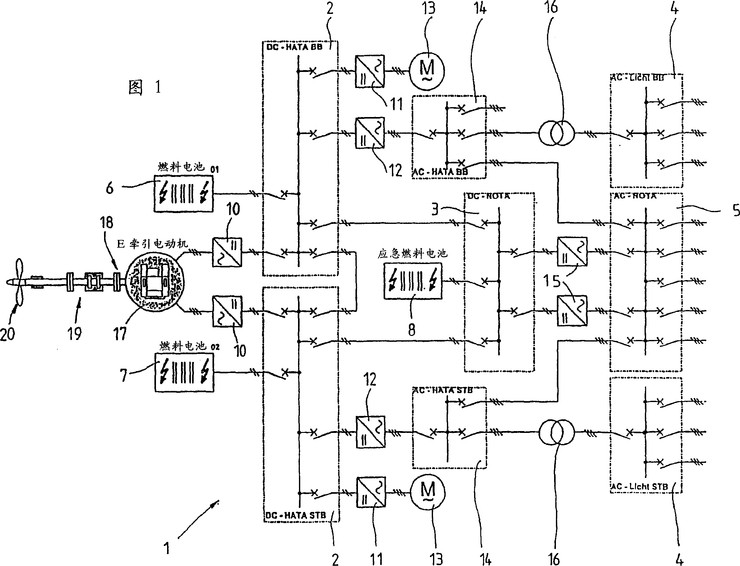
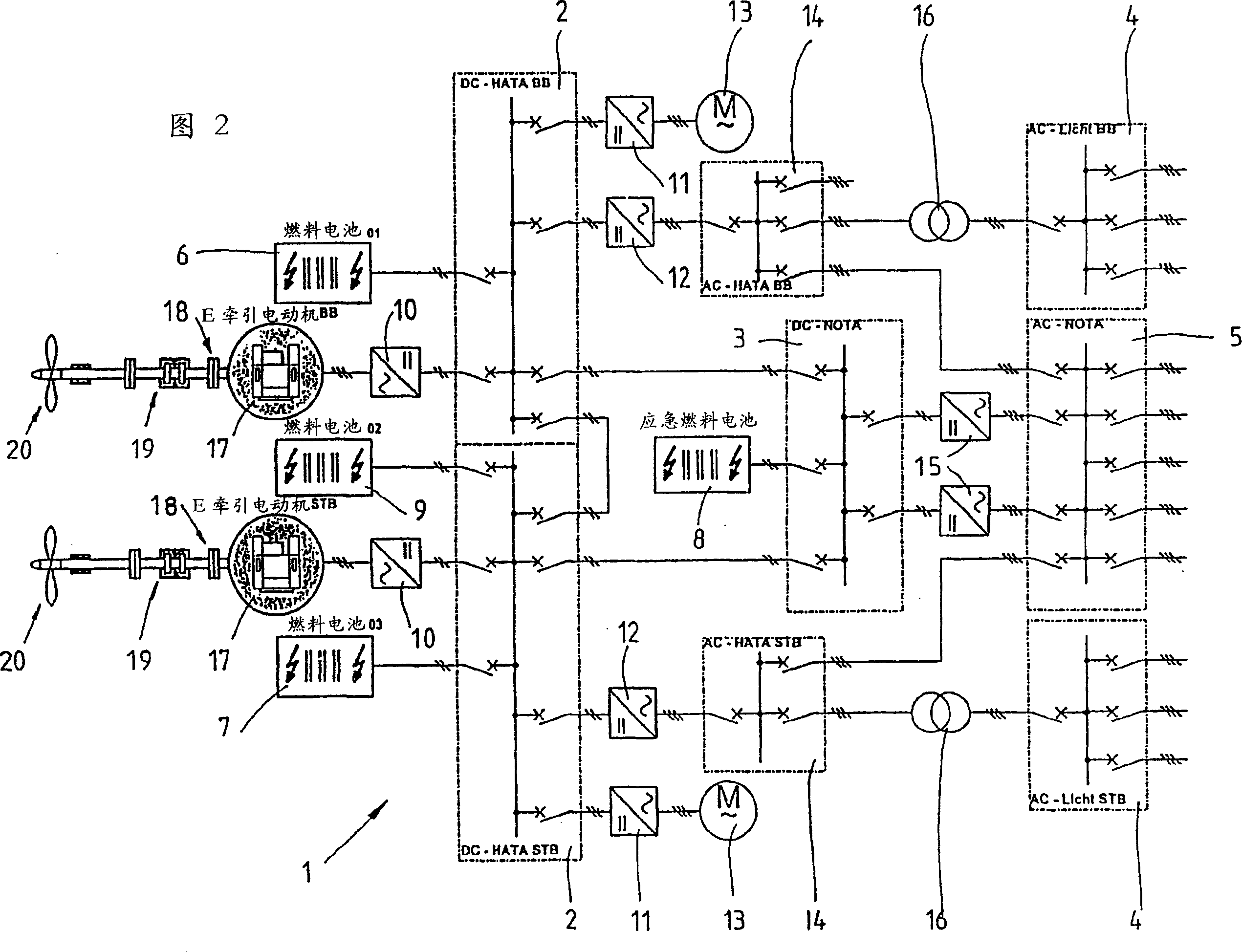
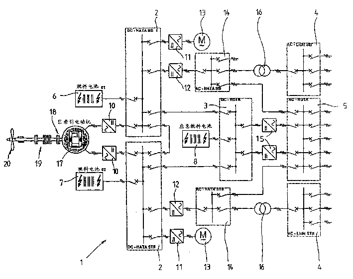
[0024] 1 and 2 each show an embodiment of an energy system 1 of a watercraft. According to FIG. 1 the energy system 1 is used for a single-propeller vessel and comprises a corresponding electric drive 17 which drives a vessel propeller 20 via a shaft 18 with a thrust bearing 19 . FIG. 2 shows an energy system 1 for a twin-screw boat, wherein an electric drive 17 is arranged on the rear side of the boat and on the rudder side respectively, and the electric drive drives a boat propeller via a shaft 18 and a thrust bearing 19 respectively. 20.

[0025] The electric drive 17 in FIGS. 1 and 2 is connected via a three-phase AC grid to the DC grids 2 on the rear side and the rudder side of the ship, each DC grid 2 consisting of at least one fuel cell module 6 and 7 or 6, 7 and 9 provide electric energy. Here, the direct current network 2 comprises a plurality of switching elements, which are connected, depending on the required power, to a control device not explicitly shown here, ...


PUM


Abstract

The invention relates to an energy system for watercraft, comprising at least one fuel cell module (6,7,8,9), preferably a H2O2 fuel cell module, by which at least one electric drive (17) and at least one electrical consumer are supplied with electric energy via a supply network. Said electrical drive (17) is an AC drive that is connected to a DC network (2) of the supply network via at least one power inverter (10).

Description

technical field [0001] The invention relates to an energy system for marine vehicles, in particular for ships, submarines and the like. Background technique [0002] Known watercraft of various types and sizes are generally driven by fixed propellers, adjustable propellers, control propellers (Ruderpropeller) and occasionally also by water jet systems. In this case, the mechanical energy for the drive is generated directly from an internal combustion electric motor, such as an Otto motor, a diesel motor running on heavy or light oil, or a gas turbine. Fossil fuels, which are stored in tanks carried by the watercraft, are used here as energy carriers in each case. [0003] Here, the internal combustion motors on board watercraft are used not only for drive, but also for generating electrical energy for many electrical consumers on board watercraft, for example for auxiliary drives which also convert electrical energy into mechanical energy, for electrical appliances producin...

Claims


Application Information

Patent Timeline
Patent Type & Authority Applications(China)
IPC IPC(8): B63G8/08B63H21/17H01M8/04537H01M8/04955H01M8/0612H02J4/00
CPCH01M8/0612H02J4/00B63G8/08Y02T90/38H01M2250/20Y02T90/32B63H2021/003H01M8/04604H02J2001/004H01M8/04955B63H21/17Y02T70/5209Y02T70/5236Y02T90/46B60L2200/32H02J2300/30H02J2310/42Y02T70/50Y02T90/40Y02E60/50H02J1/10
Inventor 沃尔夫冈·扎德基
Owner SIEMENS AG
Why Eureka
Try Eureka