Centrifugal type oil fume filter and purification apparatus
A technology of oil fume filter and purification device, applied in the direction of oil fume removal, heating method, separation method, etc., can solve the problems of bulky, expensive, troublesome, etc., and achieve the effect of reducing air pollution, avoiding pollution, and preventing pollution
- Summary
- Abstract
- Description
- Claims
- Application Information
AI Technical Summary
Problems solved by technology
Method used
Image

Examples
Embodiment 1
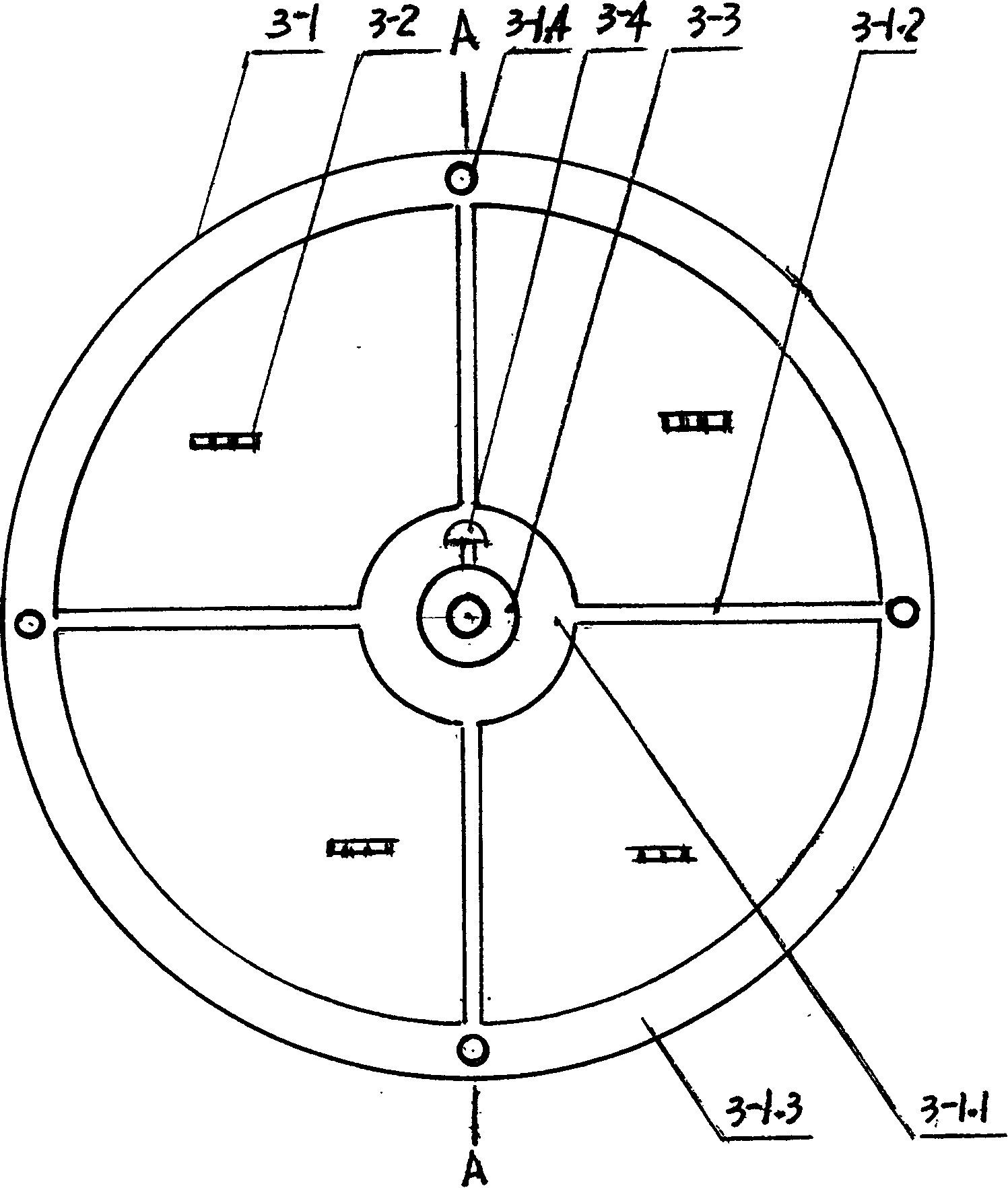
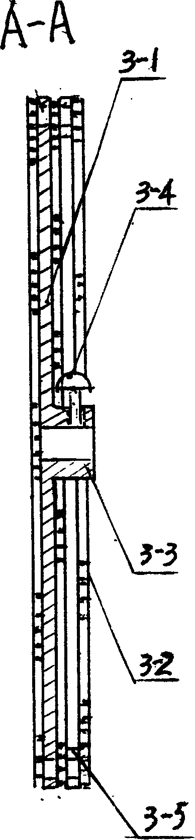
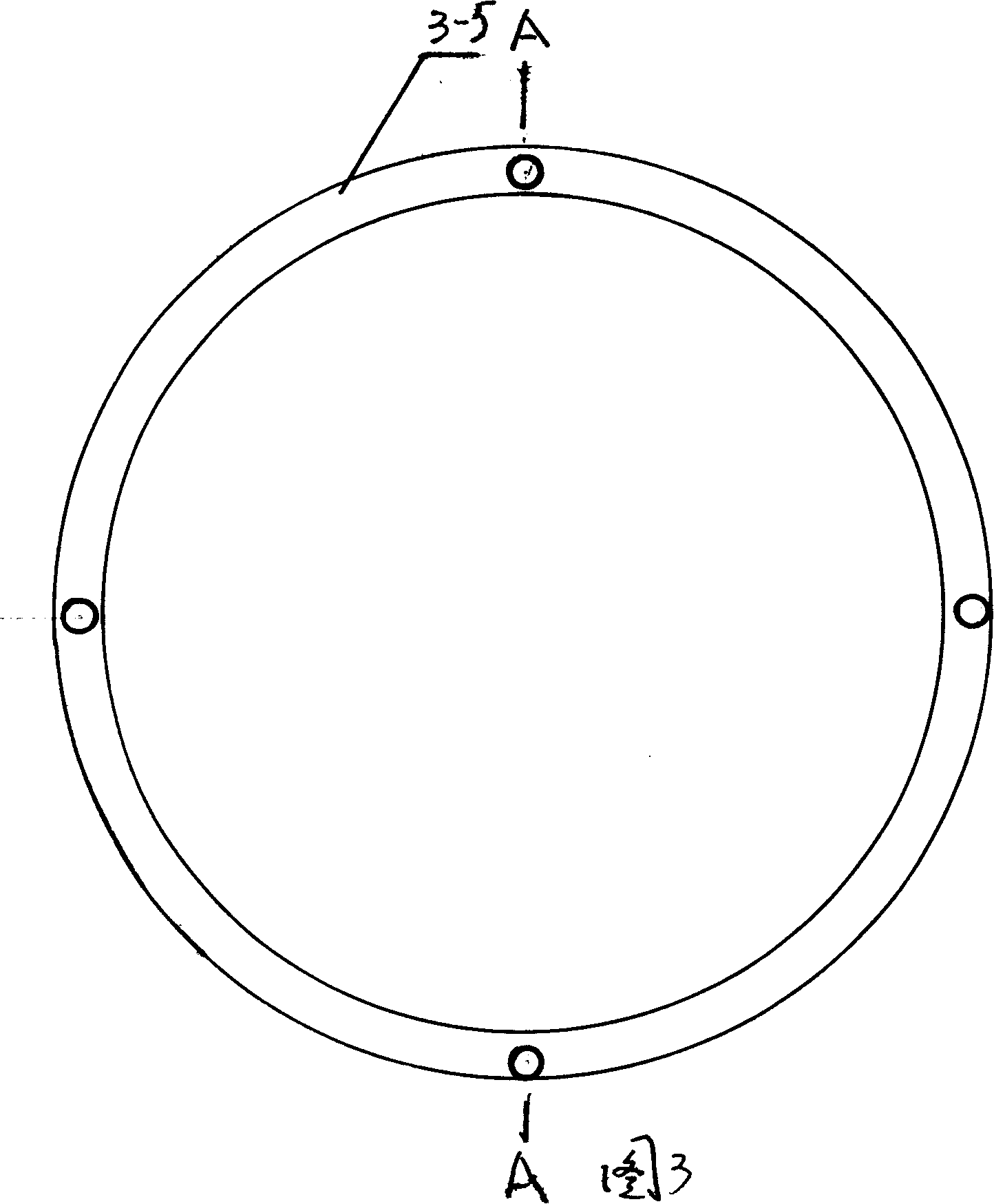
[0030] Embodiment 1, reference figure 1 - Fig. 4, this is a kind of specific structure of centrifugal oil fume filter 3, by figure 1 , figure 2 It can be seen that it consists of a circular support 3-1, a flat pad 3-5, a filter screen 3-2, a shaft sleeve 3-3 that can be sleeved on the motor shaft, and a set screw 3-4 located on the shaft sleeve. . The circular support 3-1 is composed of an inner skeleton 3-1.1, four connecting ribs 3-1.2 and an outer skeleton 3-1.3. The filter screen 3-2 has three layers, the distance between each layer is 1-4mm, and the mesh diameter is 0.8-2.5mm. One layer is located at the back of the circular support, and the other two layers are located at its front. There is a flat pad 3-5. The structure of flat pad 3-5 is shown in Figure 3 and Figure 4, and it is a ring with a fixing hole. The shaft sleeve 3-3 is welded together with the inner frame 3-1.1. Three layers of filter screens 3-2 and flat pads 3-5 and circular support 3-1 pass through ...
Embodiment 2
[0031] Embodiment 2, refer to Figure 5-Figure 7 , while referring to figure 1 -Figure 4. This is a purification device using the centrifugal oil fume filter described in Example 1, and its structural diagram is as follows Figure 5 As shown, compared with Embodiment 1, an oil retaining body 2 for accommodating the centrifugal fume filter is added. The structure of the oil retaining body 2 is as follows Image 6 , Figure 7 As shown, the oil retaining body is composed of a front rib 2-2, a rear rib 2-5 and an annular oil collecting side 2-3 connected to the front and rear ribs, and the bottom of the annular oil collecting side has a leak Oil holes 2-4. The front and rear ribs and the annular oil collection side form an annular oil collection groove 2-8, and the collected oil is finally concentrated to the bottom of the annular oil collection groove 2-8, and can flow to the oil collection box 2 through the oil leakage hole 2-4 at the bottom -6 within. It should be furthe...
Embodiment 3
[0032] Embodiment 3, reference figure Figure 8 , Figure 9 , while referring to Figure 1-Figure 7 . This is the second purification device using the centrifugal oil fume filter described in Embodiment 1. Compared with Embodiment 2, the main structure has not changed, but only the safety cover 1 is connected and fixed on the outside of the front rib of the oil deflector 2 , the connection method here is welding. Compared with embodiment 2, the security is increased.
PUM
 Abstract
Description
Claims
Application Information
 - R&D
- Intellectual Property
- Life Sciences
- Materials
- Tech Scout
- Unparalleled Data Quality
- Higher Quality Content
- 60% Fewer Hallucinations
Browse by: Latest US Patents, China's latest patents, Technical Efficacy Thesaurus, Application Domain, Technology Topic, Popular Technical Reports.
© 2025 PatSnap. All rights reserved.Legal|Privacy policy|Modern Slavery Act Transparency Statement|Sitemap|About US| Contact US: help@patsnap.com