Drive mechanism and movable working table assembly containing the same

一种驱动机构、工作台的技术,应用在驱动装置、机械设备、金属加工机械零件等方向,能够解决驱动机构刚性低等问题

Inactive Publication Date: 2004-06-02
SANKYO SEISAKUSHO
View PDF1 Cites 11 Cited by
  • Summary
  • Abstract
  • Description
  • Claims
  • Application Information

AI Technical Summary

Problems solved by technology

Therefore, if the drive mechanism has a long stroke, the stress path is also long and the stiffness of the drive mechanism is very low

Method used


Image

  • Drive mechanism and movable working table assembly containing the same
  • Drive mechanism and movable working table assembly containing the same
  • Drive mechanism and movable working table assembly containing the same

Examples


no. 1 example

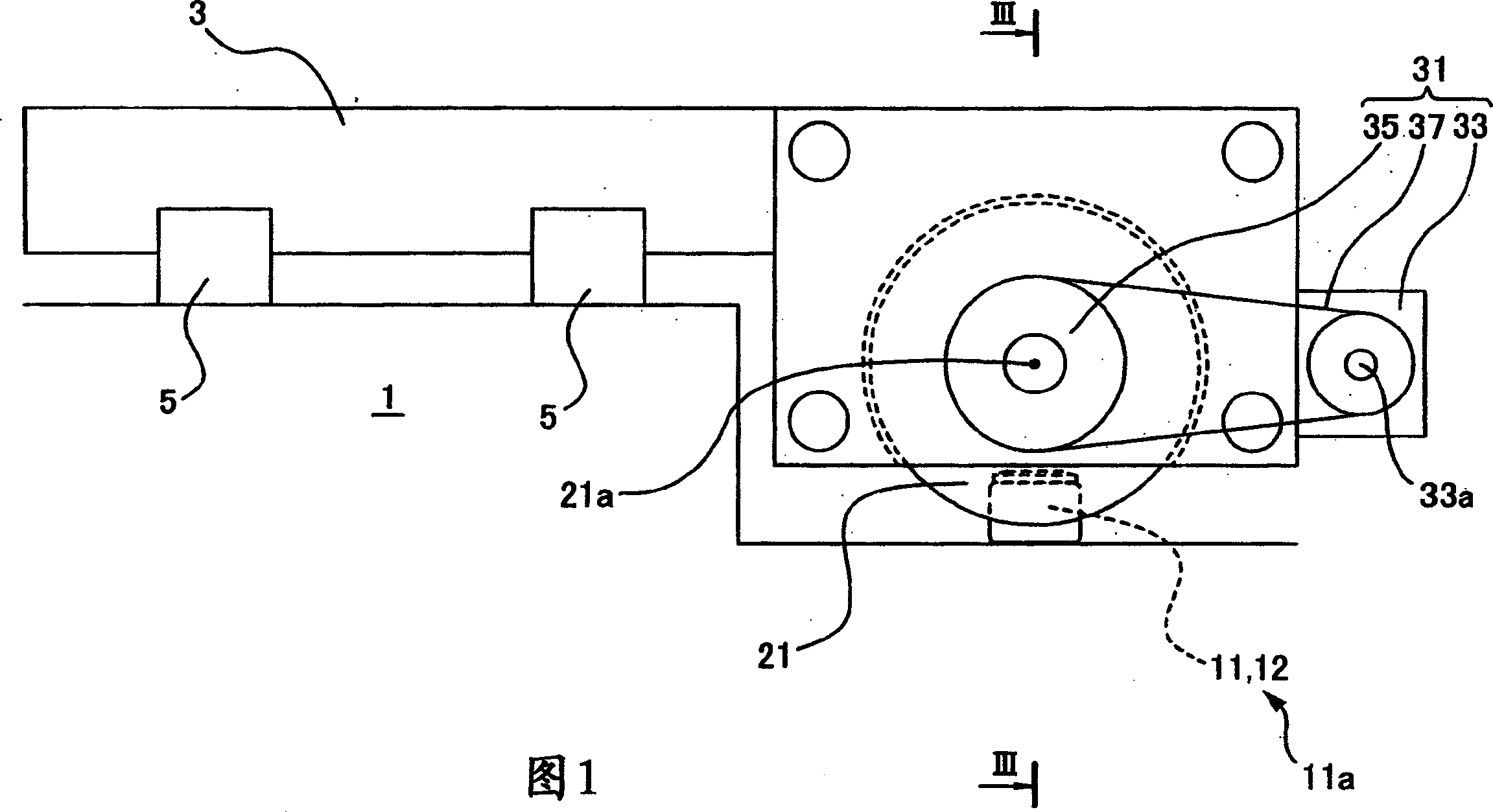
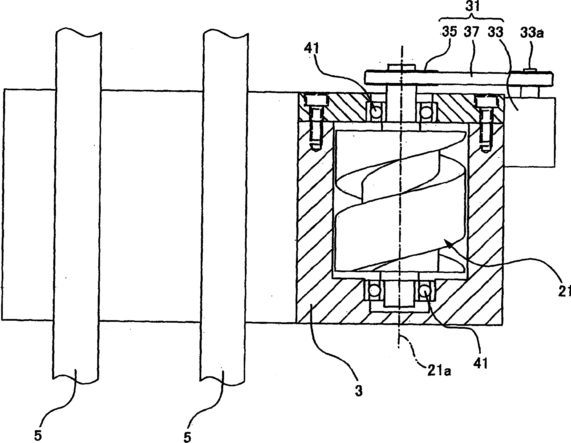
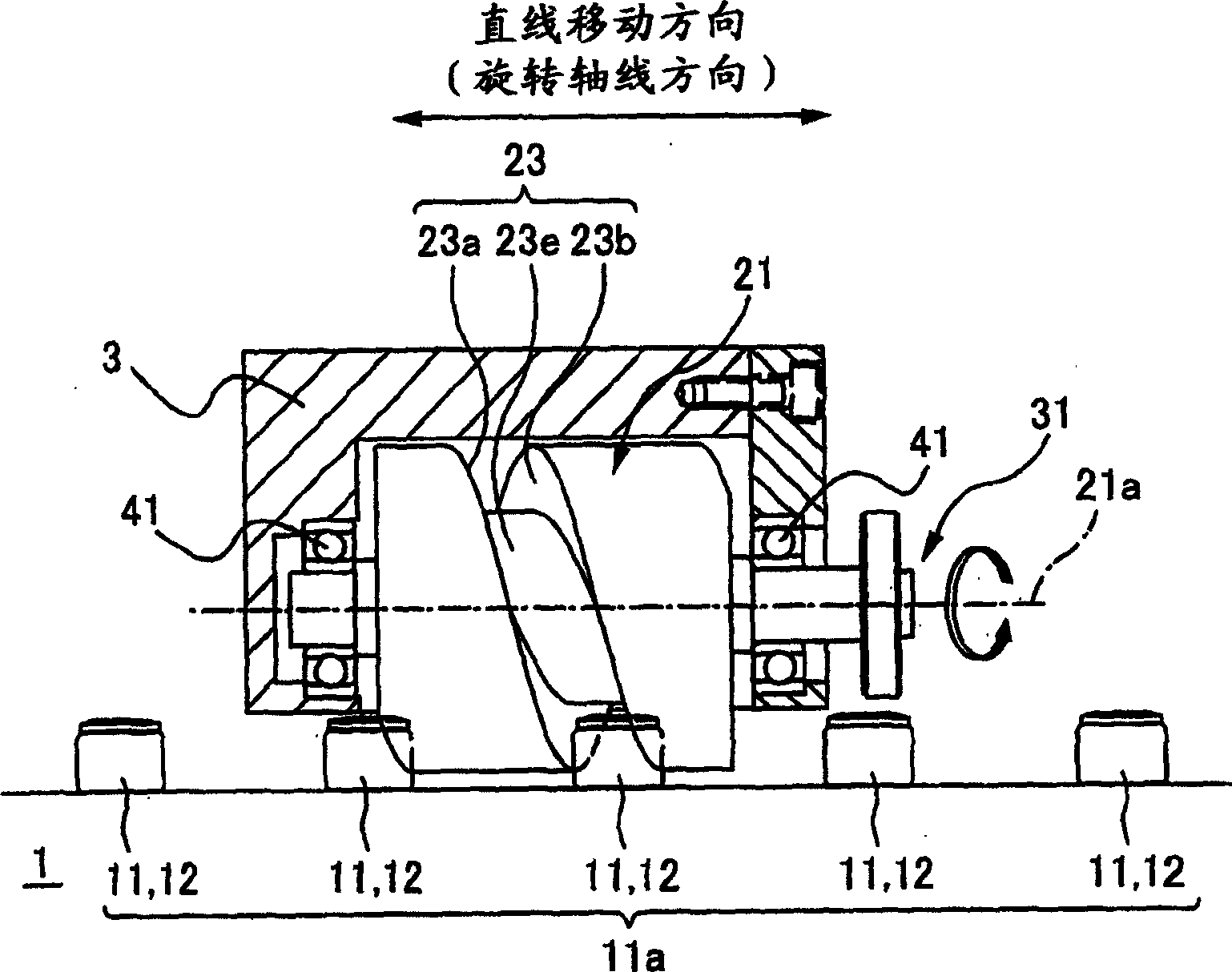
[0059] According to a first embodiment of the invention, a drive mechanism is placed between two elements to move the two elements relative to each other, at least one of the two elements is guided to move linearly in a linear direction of movement, the drive The mechanism includes: a plurality of rolling cam followers arranged in a linear movement direction and spaced apart from each other rotatably supported on one of the two elements; and another rotatably supported in the two elements A cam on an element is provided with a cam groove engaged with a rolling cam follower on its periphery, and the rotation axis of the cam is set in the direction of linear movement; by driving the cam to rotate and making the rolling cam follower continuously engage in the cam groove Centered and moved in the direction of the axis of rotation, the two elements move relative to each other.

[0060] When a cam supported on the other member is driven to rotate, a rolling cam follower supported on...

no. 2 example

[0102] Figure 4A with 4B Shows a sectional view of a drive mechanism moving a movable member 3 according to the second embodiment of the present invention, which is the same as Figure 3A with 3B similar. Figure 5 Part V in Fig. 4 is shown. Figure 6A , 6B and FIGS. 7A to 7D are views focusing on explaining the driving maneuver of the second embodiment in which the gap is eliminated. exist Figure 5 And in FIGS. 7A to 7D , in order to clearly show how the cam follower 11 and the cam groove 23 contact each other, a section of the cylindrical cam 21 taken along its center is shown. Structural components similar to those of the drive mechanism of the first embodiment are denoted by the same reference numerals, and descriptions thereof will be omitted.

[0103] Whereas the drive mechanism in the first embodiment is based on a one-point drive system with only one cam follower 11 engaging the cam groove 23, the drive mechanism in this second embodiment is based on two cam f...

no. 3 example

[0123] The driving mechanism in the first and second embodiments is provided with cam followers 11 arranged in only one cam follower row 11a, whereas the driving mechanism in this third embodiment is provided with cam followers arranged in two rows. Cam followers 11 of row 11a. More specifically, the two cam follower rows 11a and 11b extend parallel to each other in the linear movement direction of the movable member 3, as shown in FIGS. 10 to 15 .

[0124] Figures 10 to 15 respectively show several different ways of having two rows of cam follower rows. In FIGS. 10 to 15, structural components corresponding to those of the first and second embodiments are denoted by the same reference numerals, and descriptions thereof will be omitted.

[0125] Angular arrangement of cam follower rows around cylindrical cams

[0126] Figures 10 and 11 show two angular arrangements of the cam follower row around the cylindrical cam.

[0127] In the angular arrangement of the cam-follower ro...


PUM


Abstract

A drive mechanism is interposed between two members to make the members move relatively with respect to each other. At least one of the two members is guided to move linearly. The drive mechanism comprises: cam followers that are rotatably supported on one of the two members, that are arranged in the linear moving direction, and that are spaced from each other; and a cam that is rotatably supported on the other one of the two members and that is provided in its circumference with a cam groove in which the cam followers engage, the rotation axis of the cam being arranged in the direction of the linear moving direction. The two members are made to move relatively with respect to each other by driving the cam to rotate and making the cam followers engage successively in the cam groove and move in the direction of the rotation axis.

Description

[0001] related application [0002] This application claims priority from Japanese Patent Application No. 2002-309760 filed on October 24, 2002 and Japanese Patent Application No. 2003-349888 filed on October 8, 2003, the contents of which are incorporated herein by reference. Background technique [0003] technical field [0004] The present invention relates to a drive mechanism placed between two elements, the drive mechanism is used to guide the relative linear motion of the elements to each other so that the two elements move relative to each other, and also relates to a drive mechanism provided with the above-mentioned drive mechanism movable table components. [0005] Description of related technologies [0006] A movable table assembly used in a processing machine tool, such as a machining center, will refer to FIGS. 20 and Figure 21 to describe. Figure 20 is a front view of a movable table assembly 7 used on a machine tool, Figure 21 It is a cross-sectional ...

Claims


Application Information

Patent Timeline
Patent Type & Authority Applications(China)
IPC IPC(8): B23Q1/26B23Q1/58B23Q5/34F16H1/06F16H25/10F16H25/12F16H25/24
CPCY10T74/19828Y10T74/19656B23Q1/58Y10T74/18056F16H25/12Y10T74/18312F16H25/2261B23Q5/341Y10T74/18792B23Q1/26
Inventor 加藤平三郎
Owner SANKYO SEISAKUSHO
Why Eureka
Try Eureka