Hydraulic control system for automatic transmission

A technology of automatic transmission and oil pressure control, which is applied in transmission control, components with teeth, belts/chains/gears, etc., and can solve problems such as complex circuit composition and unfavorable device compactness

Inactive Publication Date: 2004-06-02
AISIN AW CO LTD +1
View PDF0 Cites 11 Cited by
  • Summary
  • Abstract
  • Description
  • Claims
  • Application Information

AI Technical Summary

Problems solved by technology

[0005] However, for example if figure 1 Shown in the hydraulic control device of the automatic transmission mechanism 10, such as figure 2 As shown in the operation table, for example, in the case of a 5-speed shift, the engagement pressure is supplied to the 1st to 3rd gears that require brake engagement and the 5th gear, and the 4th gear that is directly engaged by the input shaft and output shaft of the automatic transmission (The so-called "direct gear"), the function of blocking the engagement pressure in order to release the engagement of the brakes involved in the shift is only greatly dependent on the above-mentioned 1 set of linear solenoid valves and control valves.
Therefore, adequate countermeasures are required when malfunctions such as valve sticking occur in these valves, and the countermeasures adopted complicate the circuit configuration and are not conducive to the realization of compactness of the device.

Method used


Image

  • Hydraulic control system for automatic transmission
  • Hydraulic control system for automatic transmission
  • Hydraulic control system for automatic transmission

Examples


Embodiment Construction

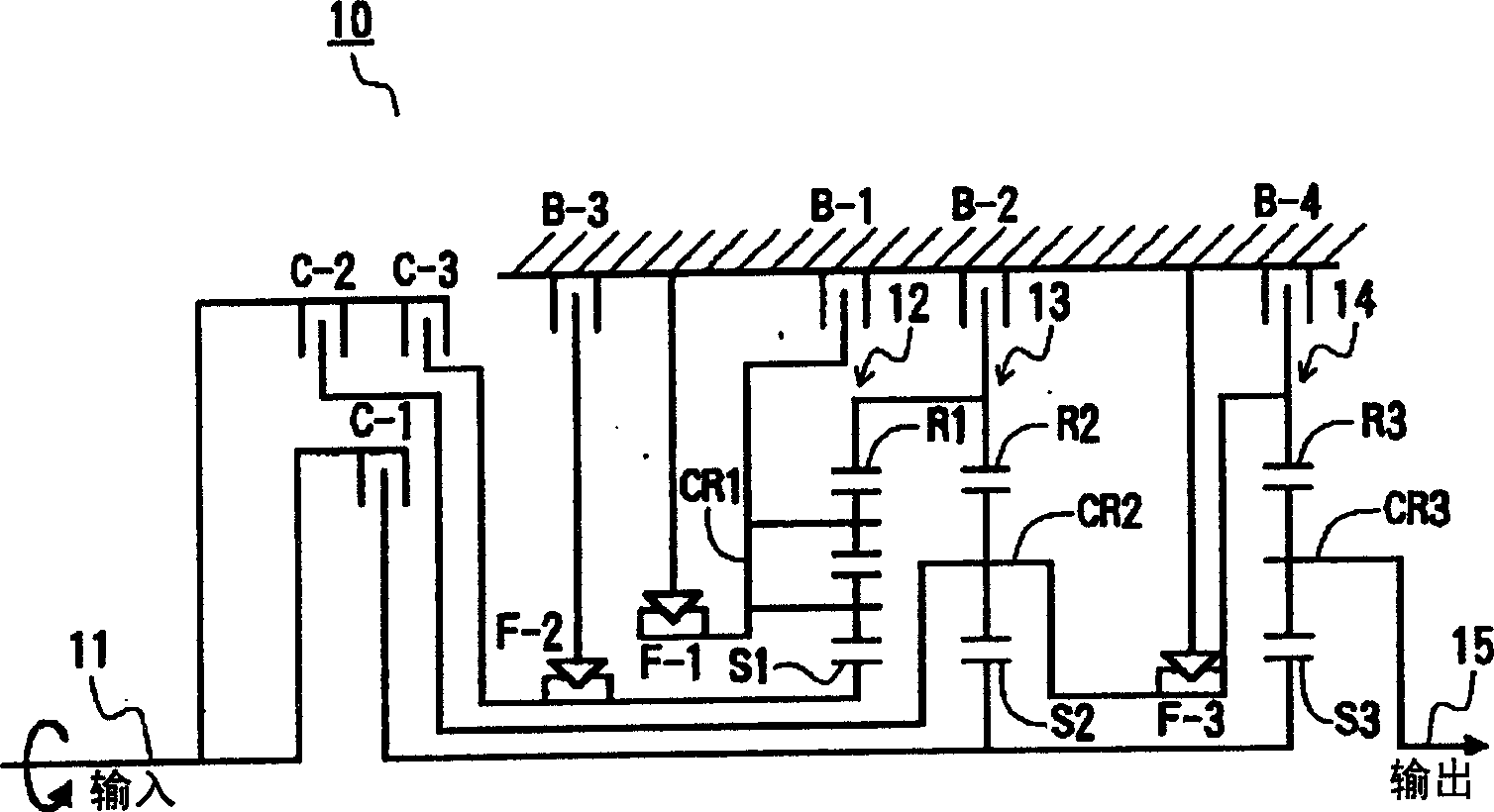
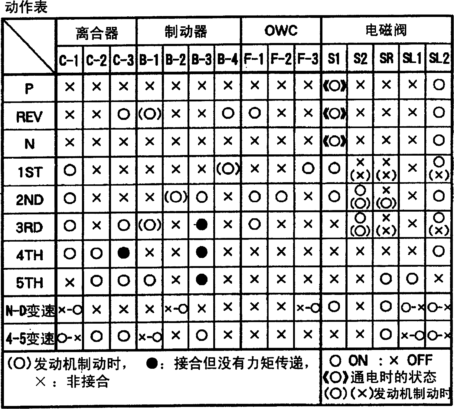
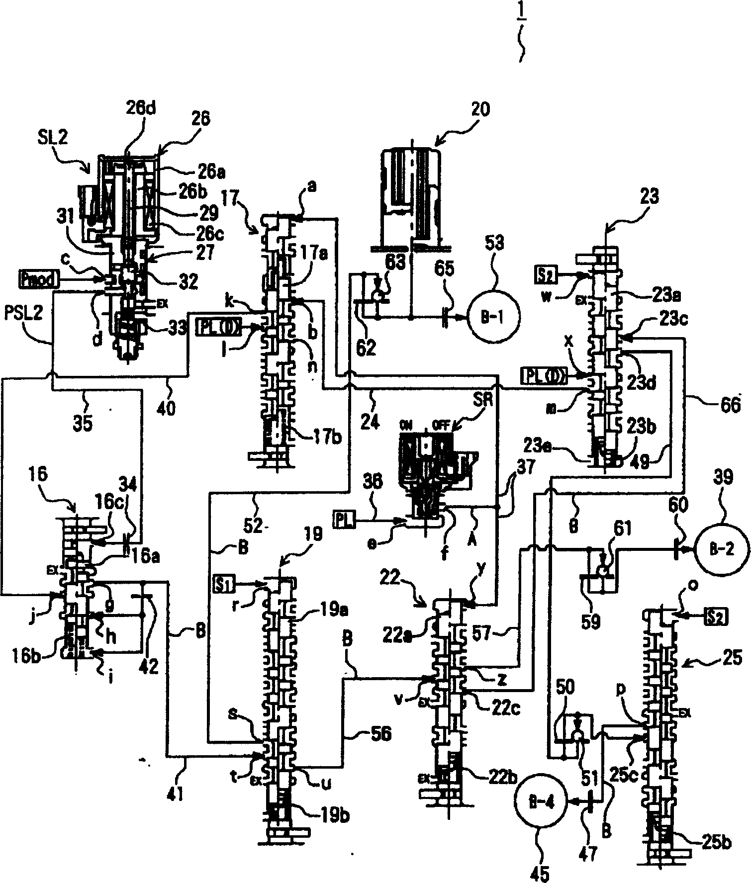
[0055] Embodiments of the present invention are described below with reference to the drawings. figure 1 is a schematic diagram showing an automatic transmission mechanism to which the present invention is applied, figure 2 It is an action table showing the action state of the automatic transmission mechanism in the transmission (D) position, image 3 It is a schematic diagram showing the hydraulic control device of the present invention.

[0056] In addition, in figure 2 In the column of clutches, brakes, and one-way clutches (OWC), (○) indicates engagement during engine braking, ● indicates engagement that does not participate in the realization of the shift speed, and × indicates non-engagement. In the display column of the solenoid valve, ○ indicates that it is in the ON state, × indicates that it is in the OFF state, (○) and (×) indicate the ON and OFF states when the engine is braked, and indicates that the ignition key is in the ON state (when the power is on ). ...


PUM


Abstract

The hydraulic control device 1 of the automatic transmission has a 3-4 shift valve 23 for outputting initial pressure of a first route at a third speed stage lower than a fourth speed stage directly connecting an input shaft 11 and an output shaft 15 of the automatic transmission and a clutch apply control valve 17 for outputting initial pressure of a second route at a fifth speed stage higher than the direct connection stage.Both valves 23 and 17 perform a control to block both initial pressures of the first and second routes at the direct connection stage.

Description

technical field [0001] The present invention relates to an oil pressure control device for an automatic transmission, in particular to an oil pressure control device for an automatic transmission that can reliably cut off the source pressure for brake engagement on a direct gear in which an input shaft and an output shaft are directly engaged. . Background technique [0002] In the prior art, there is a hydraulic control device for an automatic transmission (hereinafter also referred to as a hydraulic control device) configured in this way by selectively switching a plurality of shift valves by using a shift solenoid valve and appropriately switching the shift gear according to the operation of the shift lever. referred to only as "oil pressure control device"). Such an automatic transmission includes a plurality of frictional engagement elements such as clutches and brakes, and the frictional engagement elements corresponding to each gear stage are engaged or released in a...

Claims


Application Information

Patent Timeline
Patent Type & Authority Applications(China)
IPC IPC(8): F16H61/00F16H61/12F16H61/21F16H61/68F16H61/684F16H61/686
CPCF16H61/686F16H2061/1264F16H61/12F16H2061/122
Inventor 藤峰卓也深津彰野田和幸安藤雅彦野崎和俊金田俊树
Owner AISIN AW CO LTD
Why Eureka
Try Eureka