
Liquid crystal display

A liquid crystal display and liquid crystal display panel technology, applied in the direction of instruments, nonlinear optics, optics, etc., can solve the problem of dark bands in the visible area of ​​the liquid crystal panel, and achieve the effect of increasing the picture quality and improving the central luminance

Inactive Publication Date: 2004-06-02
AU OPTRONICS CORP
View PDF0 Cites 6 Cited by
  • Summary
  • Abstract
  • Description
  • Claims
  • Application Information

AI Technical Summary

Problems solved by technology

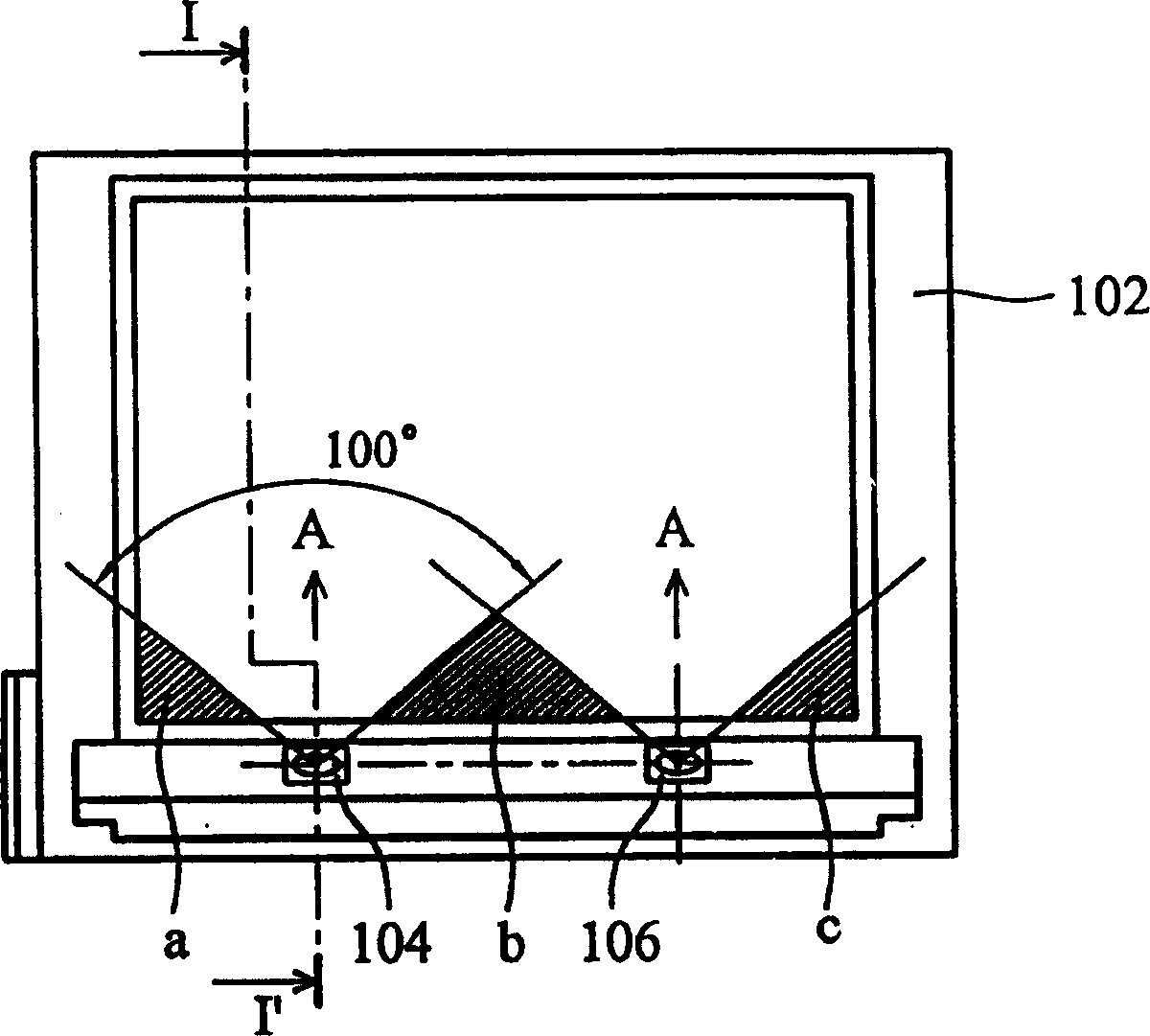
Since the light-emitting diodes have a fixed diffusion angle and the irradiation direction is parallel, there must be a local dark band between two adjacent light-emitting diodes, such as figure 1 The three areas a, b, and c on the upper part of the LCD panel cause the disadvantage of local dark bands in the visible area of ​​​​the liquid crystal panel.

Method used


Image

  • Liquid crystal display
  • Liquid crystal display
  • Liquid crystal display

Examples


Embodiment Construction

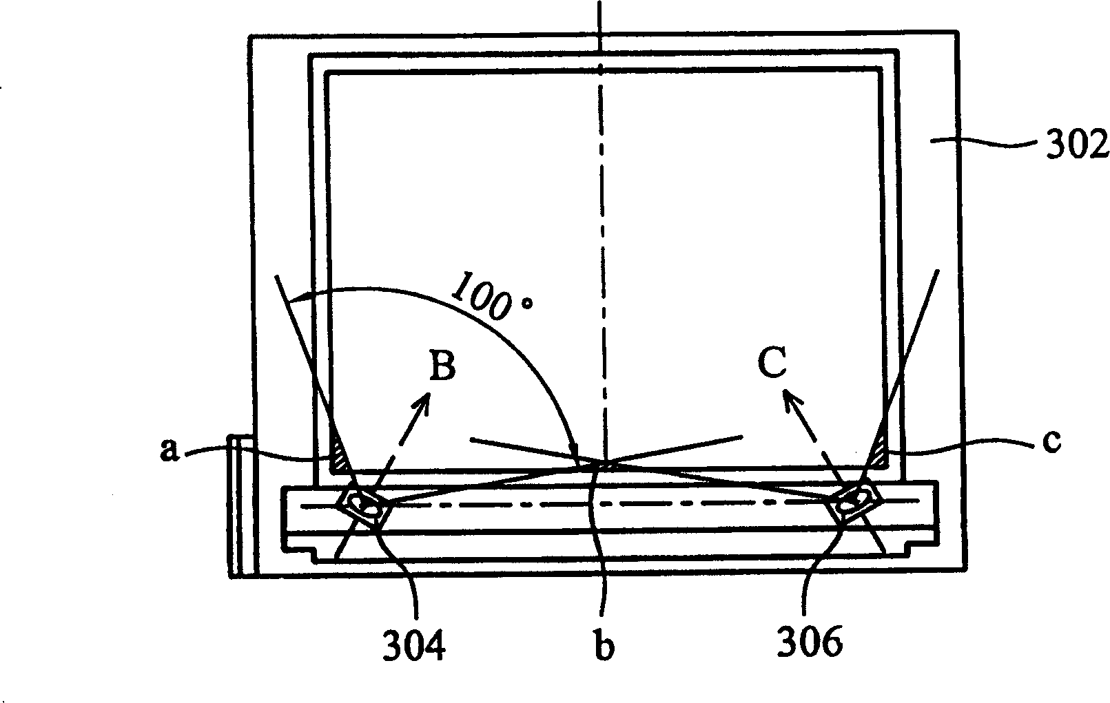
[0016] See image 3 , the liquid crystal display according to the first embodiment of the present invention will be described in detail below.

[0017] A liquid crystal display according to the present invention comprises a rectangular frame body 302 with four connected sides; a light guide plate arranged inside the rectangular frame body 302; a reflector adjacent to the light guide plate; a chemical film arranged on the reflector on-chip; the liquid crystal display panel is arranged on the chemical film and embedded in the rectangular frame 302; the light-emitting diode 304 and the light-emitting diode 306 are arranged on one of the four connected sides of the rectangular frame 302, wherein the aforementioned The light emitting diode 304 and the light emitting diode 306 have a diffusion angle of 100 degrees, the light emitting diode 304 has an illumination direction B, and the light emitting diode 306 has an illumination direction C, and the illumination direction B and the i...


PUM


Abstract

The liquid crystal display includes one rectangular frame with four sides; one light guiding plate set inside the rectangular frame; one reflecting plate adjacent to the light guiding plate; one chemical diaphragm set on the reflecting plate; one liquid crystal display panel set on the chemical diaphragm and embedded into the rectangular frame and LEDs on one side of the rectangular frame with different irradiation directions. The present invention can reduce dark bands in LCD, make homogeneous brightness in the visual area, raise the central gray and raise image quality without raising cost.

Description

technical field [0001] The invention relates to a liquid crystal display, in particular to a liquid crystal display capable of reducing the phenomenon of dark bands in the visible area of ​​a liquid crystal panel. Background technique [0002] Liquid crystal displays are widely used in portable electrical products such as electrical calculators (electrical calculators), personal digital assistants (PDAs), electronic dictionaries, and electronic books (electrical books), while light-emitting diodes ( LED) as the light source technology has the advantages of low voltage and low power consumption, and is currently the light emitting method used by many liquid crystal displays. However, this type of light source using light-emitting diodes is a point light source, which is different from the general CCFL lamp which is a line-to-surface light source. When using multiple light-emitting diodes side by side as a light source, please refer to figure 1 , the liquid crystal display in...

Claims


Application Information

Patent Timeline
IPC IPC(8): G02F1/1333G02F1/1335
Inventor 郭汉斌谢锦坤
Owner AU OPTRONICS CORP
Learn More