
Damper

A damper and flow resistance technology, applied in the direction of liquid resistance brakes, brake types, liquid shock absorbers, etc., can solve the problems of increased assembly man-hours, increased manufacturing costs, time lag, etc., to achieve fewer parts, lower manufacturing costs, The effect of reducing assembly man-hours

Inactive Publication Date: 2004-06-09
NIFCO INC
View PDF0 Cites 10 Cited by
  • Summary
  • Abstract
  • Description
  • Claims
  • Application Information

AI Technical Summary

Problems solved by technology

[0008] However, such a damper requires a large number of parts, an increase in assembly man-hours, and an increase in manufacturing cost.
In addition, due to the use of the clutch plates 106, 108 formed with the tooth portions 106A, 108A, when the rotational force is transmitted from the clutch plate 108 to the clutch plate 106, time may be caused by the meshing state of the tooth portions 106A, 108A. lag

Method used


Image

  • Damper
  • Damper
  • Damper

Examples


Embodiment Construction

[0042] A damper according to an embodiment of the present invention will be described.

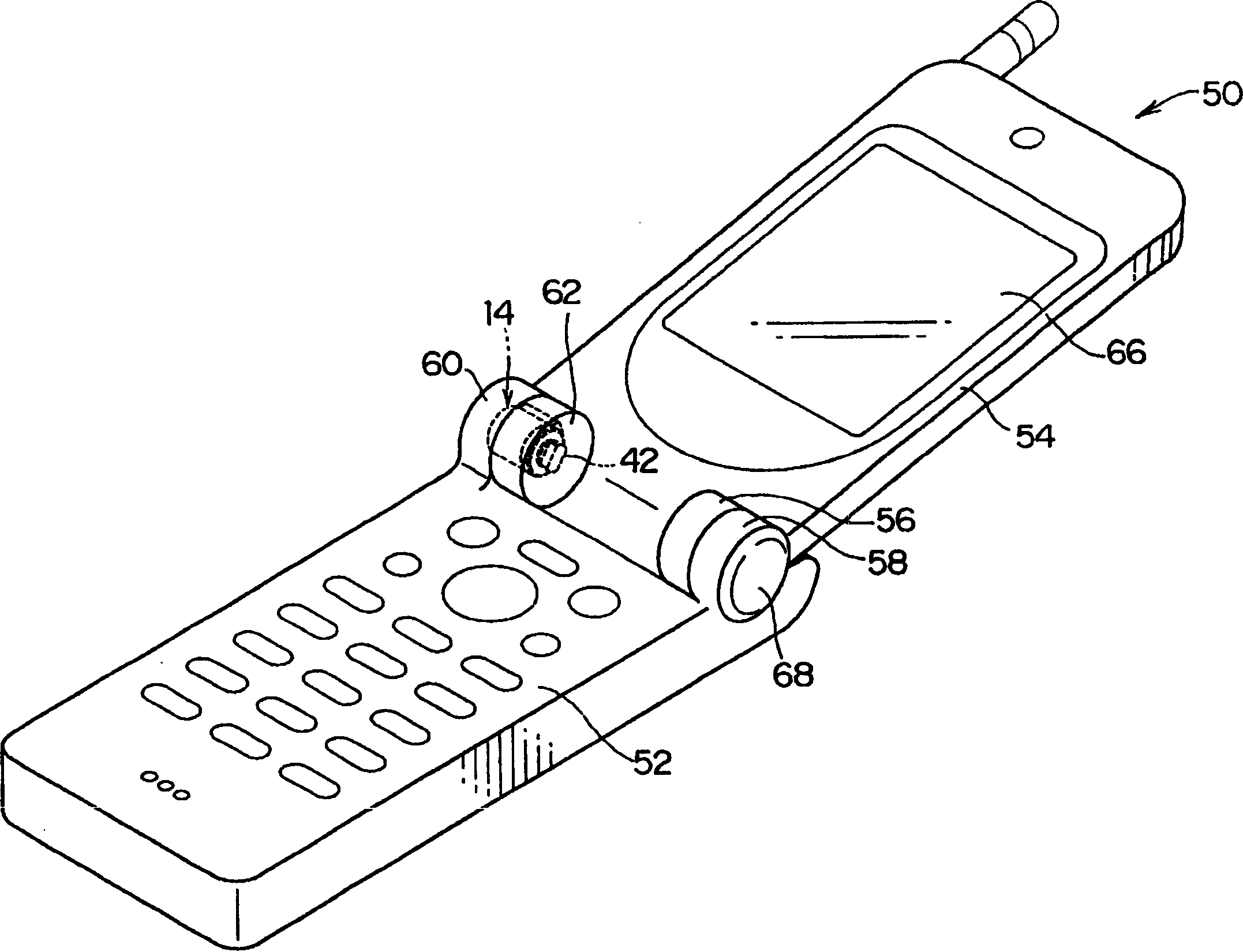
[0043] figure 1 A mobile phone 50 using the damper 14 according to the embodiment of the present invention is shown. This mobile phone 50 is constituted by a transmitting side main body 52 and a receiving side main body 54 , and a pair of shaft parts 56 and 58 and shaft parts 60 and 62 are provided on the mobile phone 50 . Therefore, the receiving-side body 54 can be rotated relative to the transmitting-side body 52 , and the mobile phone 50 can be folded with the receiving-side body 54 closed.

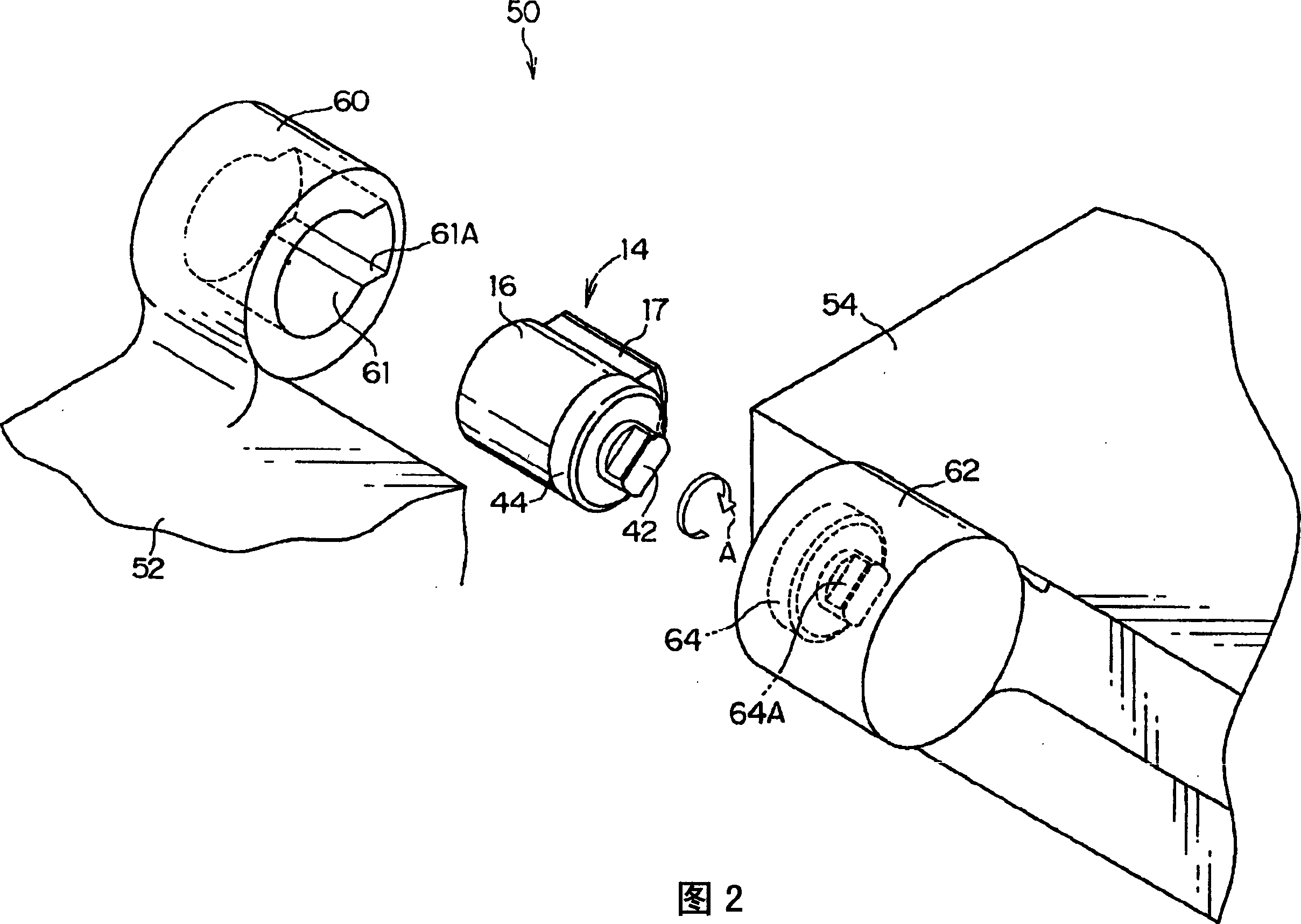
[0044] Springs (not shown) are disposed on the side of the shaft portions 56 and 58 so that the receiving-side main body 54 tends to open toward the transmitting-side main body 52 . On the other hand, the damper 14 is disposed on the side of the shaft portions 60 and 62 , and a braking force acts on the opening of the receiving-side main body 54 .

[0045] Here, the configuration of the damper...


PUM


Abstract

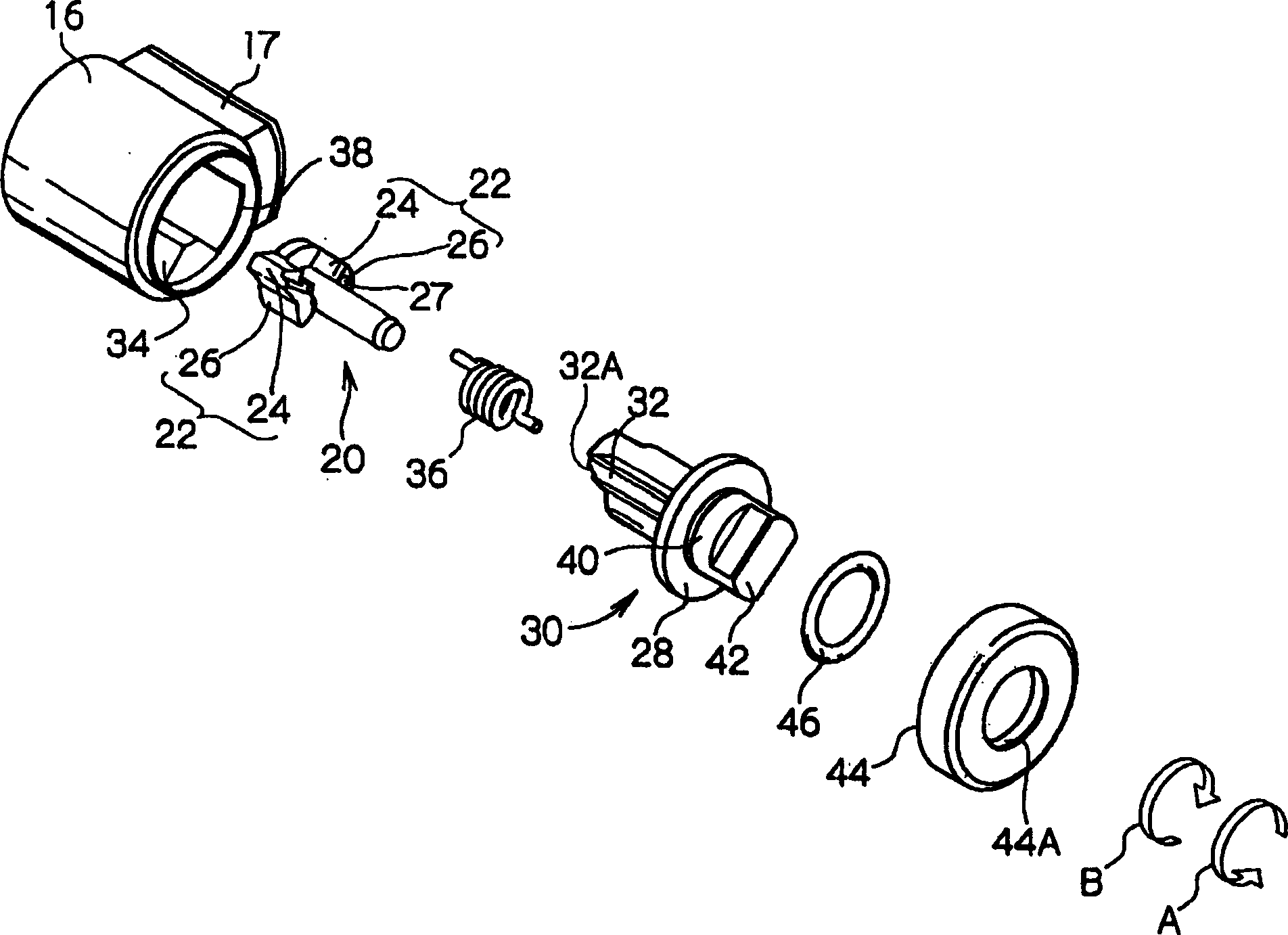
When an upper 30 is rotated in the direction of an arrow B, the connection of the upper 30 to a bottom 20 is released, and a clearance is formed between the upper 30 and the bottom 20. Accordingly, a braking force acting on the upper 30 can be reduced by passing viscous fluid through the clearance to reduce a fluid resistance caused by the viscous fluid. Also, when the upper 30 is rotated in the direction of an arrow A, the upper 30 is connected to the bottom 20 and they are integrally rotated. Thus, the braking force acting on the upper 30 can be increased by shearing resistances caused by the viscous fluid applied to a projectedly installed part 32 and a connection part 24 and the viscous fluid passed through the clearance thereof from the inner peripheral surface of a housing. As a result, the torque can be varied according to the rotational direction.

Description

technical field [0001] The present invention relates to a damper. Background technique [0002] Such as Figure 7 Shown in the official publication No. 5-89993 (page 9-13, figure 1 ), the rotor 102 is disposed inside the main body casing 100, and the gap between the main body casing 100 and the rotor 102 is filled with silicon grease (silicon grease) as a viscous fluid, and is sealed by a cap (cap) 104 . [0003] A clutch plate (clutch plate) 106 is assembled to the rotor 102 and can rotate integrally with the rotor 102 . In addition, a clutch friction plate 108 is disposed on an upper portion of the clutch friction plate 106 . Here, the cover part 105 is engaged with the cover body 104 , and the fitting part 107 protruding from the cover part 105 is exposed from a through hole formed in the center part of the cover body 104 . [0004] In addition, the clutch plate 108 is assembled to the back surface of the cover 105 , and is movable in the axial direction of the cover ...

Claims


Application Information

Patent Timeline
Patent Type & Authority Applications(China)
IPC IPC(8): F16F9/20F16D57/02F16F9/12
CPCF16D57/02F16F9/12Y10T16/2771Y10T16/276F16F9/20
Inventor 林见
Owner NIFCO INC
Learn More