Chip check apparatus

A technology for inspecting equipment and wafers, which is applied in the direction of instruments, semiconductor/solid-state device testing/measurement, and analyzing materials, etc. It can solve the problems of not being able to set up a swing stage, etc., and achieve increased occupied area, compact equipment structure, and high-precision wafer inspection Effect

Inactive Publication Date: 2004-06-09
OLYMPUS CORP
View PDF2 Cites 31 Cited by
  • Summary
  • Abstract
  • Description
  • Claims
  • Application Information

AI Technical Summary

Problems solved by technology

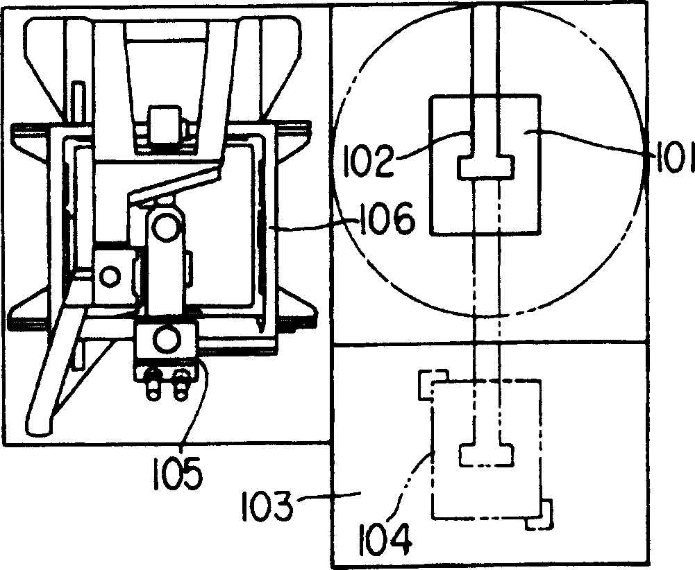
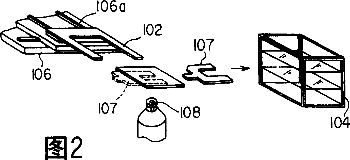
[0019] But, the inspection equipment of Japanese Unexamined Publication No. 6-229934 utilizes the concave-shaped transfer arm 102 to take out the wafer from the film cassette 104, and the convex-shaped repositioning platform 103 is raised, and after receiving

Method used


Image

  • Chip check apparatus
  • Chip check apparatus
  • Chip check apparatus

Examples


Embodiment Construction

[0033] An embodiment of the present invention will be described in detail below with reference to the drawings.

[0034] Figure 6A and FIG. 6B is a schematic diagram showing a structure of a wafer inspection apparatus according to an embodiment of the present invention, Figure 6A 6B is a front view, and FIG. 6B is a plan view.

[0035] exist Figure 6A As shown in FIG. 6B , the apparatus main body 1 has a cassette unit 2 for storing wafers 10 described below as substrates, and a wafer inspection unit 3 for inspecting the wafers 10 .

[0036]The cassette unit 2 has a cassette 4 storing a plurality of wafers 10 . The film cassette 4 has an elevating device 5 for moving the entire film cassette 4 in the vertical direction.

[0037] The wafer inspection unit 3 has a microscope 6 as an optical observation device for optically observing the wafer 10, and an XY stage 7 for placing the wafer 10 so as to be movable in the XY axis directions. This XY stage 7 has a wafer transfer ...


PUM


Abstract

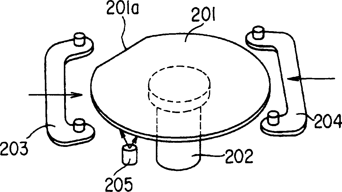
To provide a wafer inspection device which can realize an efficient configuration for suppressing an increase in footprint and can inspect a wafer with high accuracy.The wafer inspection device has a cassette part 2 and a wafer inspection part 3 including a microscope 6 and an XY stage 7 for moving the wafer 10. The cassette part 2 comprises a cassette 4 for holding the wafer 10 and an elevator 5. The wafer inspection part 3 comprises a carrying arm 18 that is arranged on the XY stage 7 to insert/extract the wafer 10 by arm pieces 181, 182 which can linearly move toward an opening of the cassette 4 and can be inserted between wafers 10 in the cassette 4, and a wafer rotary mounting base 22 which is vertically movable above the XY stage 7 to carry-in/carry-out the wafer to the carrying arm 18 by the vertical movement, a centering means for making the center of the wafer 10 and the rotary center of the wafer rotary mounting base 22 coincide with each other, and a detecting means for detecting the orientation of the wafer. (C)2004,JPO.

Description

[0001] The present invention relates to wafer inspection equipment used for appearance inspection, film thickness inspection, and the like of semiconductor wafers. Background technique [0002] In the past, wafer inspection equipment used for appearance inspection, film thickness inspection, or defect inspection of semiconductor wafers mostly adopted the following structure, including: a microscope with an XY stage, a transfer manipulator for transferring wafers, and a The cassette stage of wafer cassettes is composed of combinations thereof. [0003] This kind of wafer inspection equipment basically consists of microscopes, transfer manipulators, and cassette tables as independent units, and these units are combined to form a system, which can freely configure each unit and select models. Effect. [0004] figure 1 It is a figure which shows the 1st conventional example (refer to Unexamined-Japanese-Patent No. 6-229934). figure 1 An example of using a liquid crystal glass s...

Claims


Application Information

Patent Timeline
IPC IPC(8): G01B11/30G01N21/01G01N21/88H01L21/66H01L21/68
Inventor 秋叶彻土坂新一
Owner OLYMPUS CORP
Why Eureka
Try Eureka