Shaping mould device

A technology for forming molds and molds, applied to the structure of telephones, etc., can solve problems such as rising costs

Inactive Publication Date: 2004-06-16
FUJISU I NETWORK SYST
View PDF1 Cites 3 Cited by
  • Summary
  • Abstract
  • Description
  • Claims
  • Application Information

AI Technical Summary

Problems solved by technology

Because, in this forming die device, the shapes and areas of the contact front ends of the punching blocks 63, 64 must be equal, so it is neces

Method used


Image

  • Shaping mould device
  • Shaping mould device
  • Shaping mould device

Examples


Embodiment Construction

[0025] Hereinafter, referring to the figures, embodiments of the molding die device of the present invention will be described in detail.

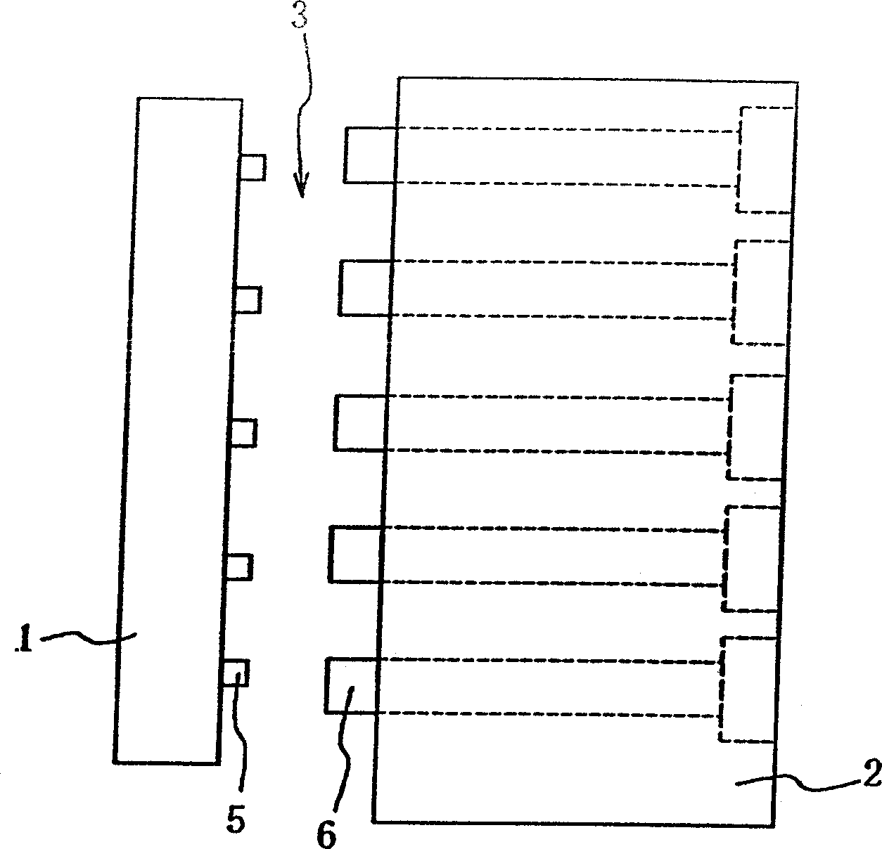
[0026] figure 1 What is shown is a schematic structural view of the forming mold device of the first embodiment of the present invention. In this embodiment, in order to make a plastic film molded body with a large number of openings with dense openings, the female mold side contact plug 5 and the male mold 2 are set on each part of the female mold 1 and the male mold 2 that shape the opening of the molded body. Die side touch pin 6. The touch pin 5 on the female mold side and the touch pin 6 on the male mold side are protrusions protruding into the mold cavity 3 and touching each other.

[0027] The front surface area of ​​the touch pin 5 on the female mold side is smaller than that of the touch pin 6 on the male mold side, and the length of the touch pin 5 on the female mold side protruding into the mold cavity 3 is also smaller than ...


PUM


Abstract

Provided is a mold assembly which improves the surface finish properties and durability of a molded object and can be manufactured simply at a low cost. This mold assembly is used for manufacturing a molded object with an opening by clamping a cavity-side part 1 and a core 2 and injecting a molten resin into the cavity 3 formed between the cavity-side part 1 and the core 2. In this mold assembly, projected parts 5 and 6, which are projected into the cavity 3 to collide with each other in the clamped state of the cavity-side part 1 and the core 2, are provided to the respective parts of the cavity-side part 1 and the core 2 for molding the opening and at least the opposed end areas of the paired projected parts 5 and 6 are differentiated.

Description

technical field [0001] The present invention relates to a molding die device suitable for manufacturing a molded body having openings, especially a molded body having a large number of dense openings such as a speaker of a telephone. Background technique [0002] A known forming die arrangement is, for example, having image 3 The schematic structure shown. This molding die device includes a female mold (Cavity Mold) 51 to be the surface side of the molded body, a male mold (Core Mold) 52 to be the rear side of the molded body, and a plurality of touch pins 53 provided on the male mold 52 . By making the female die 51 and the male die 52 mold-bonded together, the touch pin 53 is brought into contact with the female die 51, and then the molten resin supplied into the mold cavity 54 between the female die 51 and the male die 52 is molded, Thus, a molded body having a large number of openings densely packed can be manufactured. [0003] Another known forming die device, such ...

Claims


Application Information

Patent Timeline
IPC IPC(8): B29C45/37B29C45/26H04M1/03
Inventor 山口纯司小野贤治
Owner FUJISU I NETWORK SYST
Why Eureka
Try Eureka