Massaging devices

一种按摩器、辊轮的技术,应用在揉捏按摩器具、滚柱按摩、振动按摩等方向,能够解决驱动时间加长等问题,达到摩擦减少、容易按摩的效果

Inactive Publication Date: 2004-07-07
MARUTAKATECHNO
View PDF1 Cites 8 Cited by
  • Summary
  • Abstract
  • Description
  • Claims
  • Application Information

AI Technical Summary

Problems solved by technology

[0003] But, because the purpose of this prior art is to stimulate the whole sole of the foot generally with the member of special shape, thereby also just simultaneously stimulated the part of the sole of the foot that is ineffective in stimulating the sole of the foot, the driving time for stimulation just has to be lengthened.

Method used


Image

  • Massaging devices
  • Massaging devices
  • Massaging devices

Examples


Embodiment 1

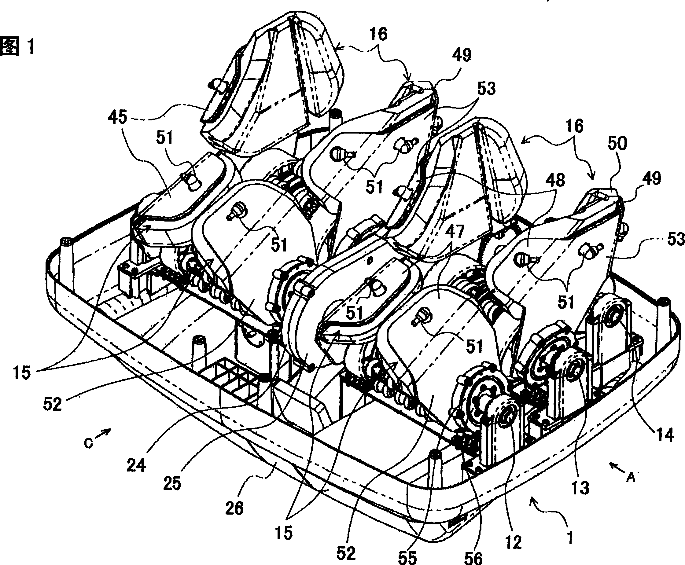
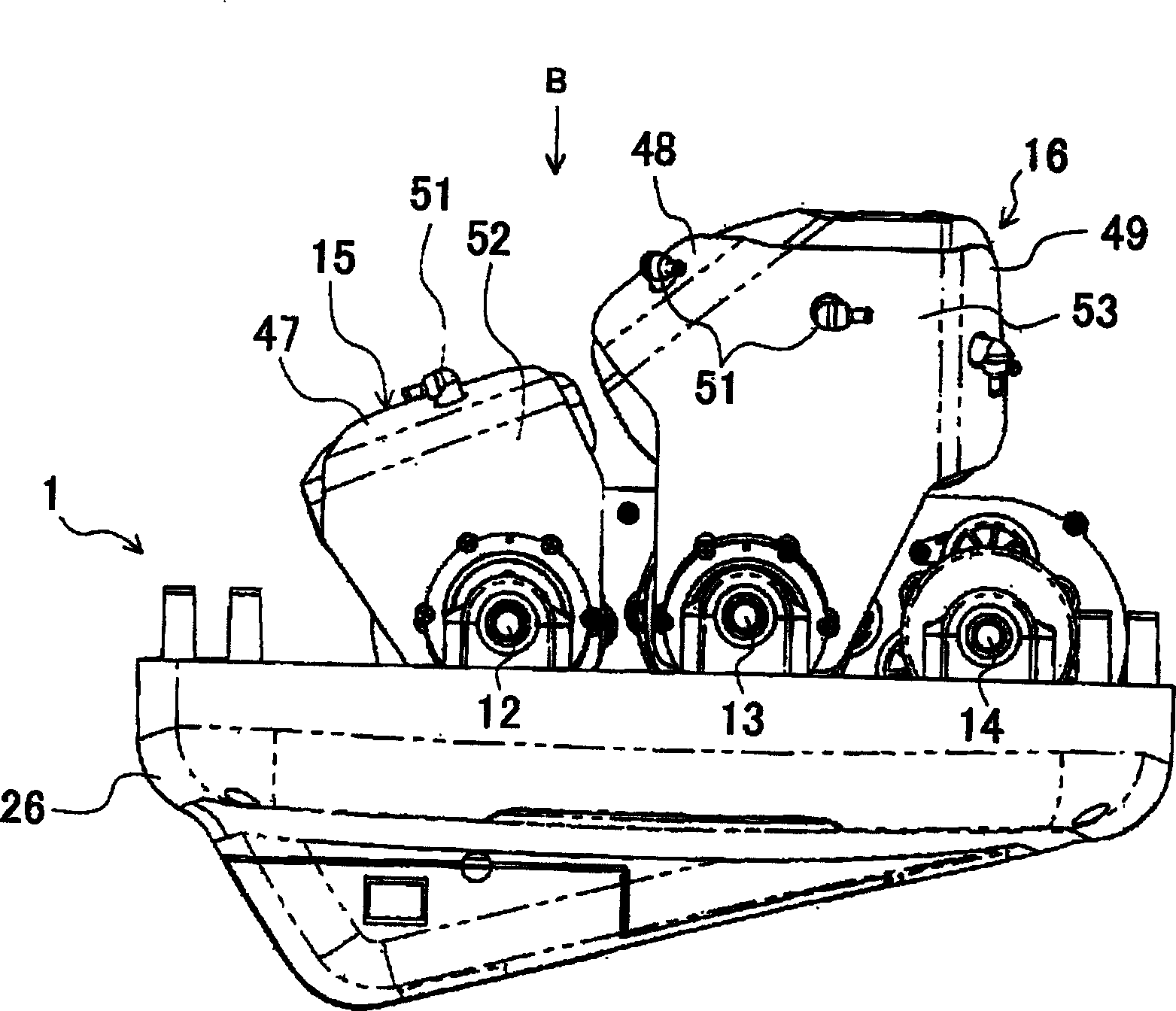
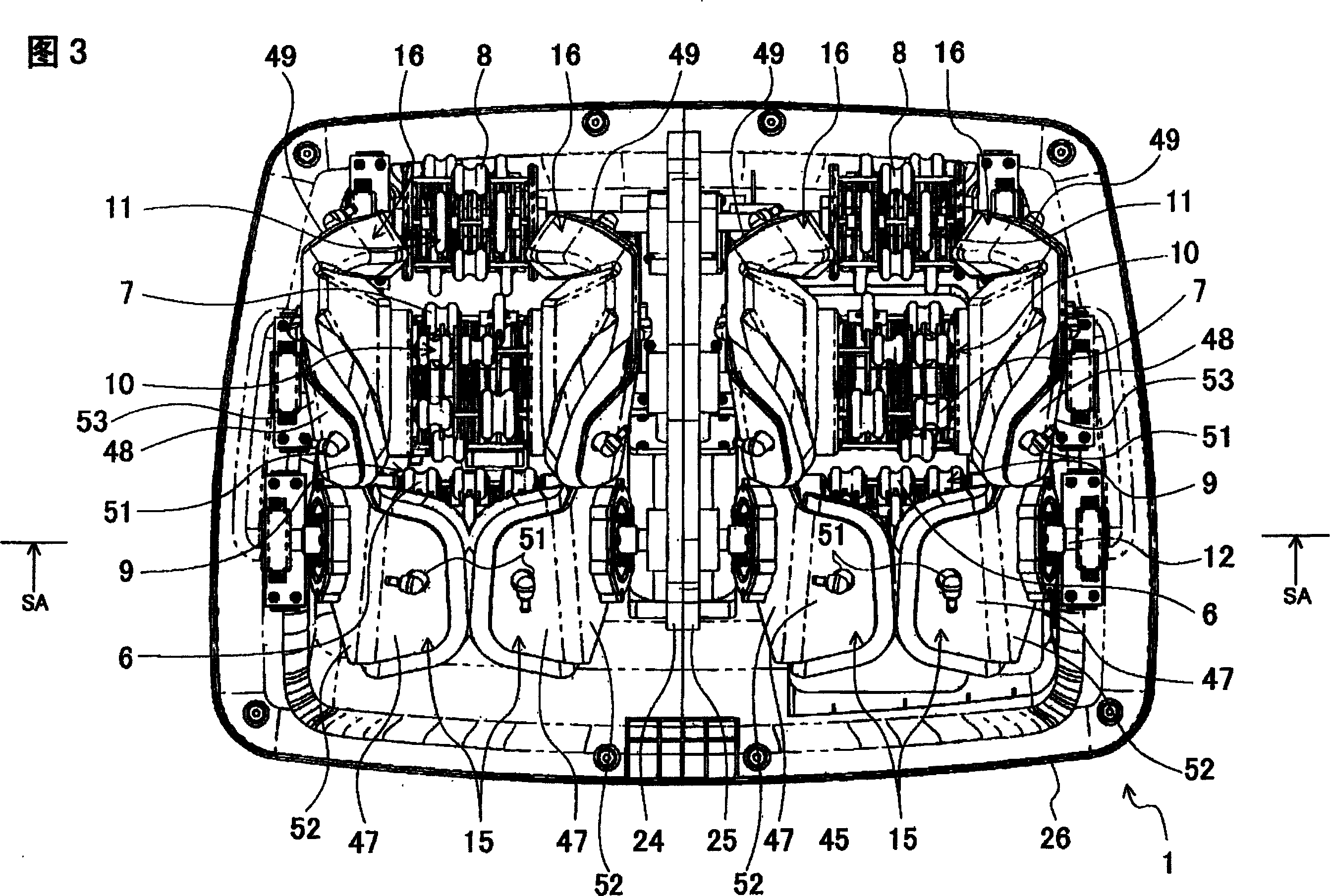
[0054] Figure 1~ Figure 25It is a schematic diagram showing the first embodiment of the present invention. The symbol 1 of Fig. 1 is a massager, and this massager 1 is provided with the roller bodies 9, 10, 11 with massage convex parts 6, 7, 8 respectively on the drive shafts 12, 13, 14, and these convex parts can only with conceived as Figure 25 The soles of the feet of the massager M, that is, the bottom side 2a of the toes 2, the soles of the feet 3, and the three parts of the heels 4, can produce contact with the soles of the feet 5 of the massager M that is higher than the general contact pressure. pressure. The drive shafts 12 , 13 , 14 are driven by the rotary drive force of the motor 18 via the rotary shaft 19 as a worm and the reduction gear 17 of the helical gears 20 , 21 , 22 . The above-mentioned roller bodies 9, 10, 11 are driven by drive shafts 12, 13, 14 so that they can rotate in a predetermined direction.

[0055] The protrusions 6, 7, 8 and the roller b...

Embodiment 2

[0073] Fig. 26 is a schematic view showing the second embodiment of the present invention. The symbol 40 in Fig. 26 is a roller body that replaces the roller body 10, so that the driving shaft 13 of the above-mentioned roller body 40 is in the drive with other roller bodies 9, 11. Shafts 12, 14 have the same height, and the driving track of the convex portion 7 of the roller body 40 for massaging the center of the foot 3 arranged only on the position facing the center of the foot 3 of the person receiving the massage M, The drive tracks for foot massage of the convex parts 6, 8 of the massage roller bodies 9, 11 disposed at positions other than the area assumed to be the center of the foot 3 of the massager M are closer to the massage part. Also make the outer diameter of the 2nd, the 3rd, the 4th roller 33,35,36 on the center of the sole 3 side than the outer diameter of the first roller 32 near the center of the foot 3 outside, thereby can massage the sole of the person M's f...

Embodiment 3

[0075] Figure 27 is a schematic diagram showing a third embodiment of the present invention, Figure 27 The symbol 41 is the roller body that replaces the roller body 10, so that the driving shaft 13 of the above-mentioned roller body 41 is at the same height as the driving shafts 12, 14 of other roller bodies 9, 11, and the The cross-sectional shape of the roller body 41 used for massaging the sole of the foot 3 on the position where the sole of the foot 3 of the person receiving the massage is assumed to be elliptical, and the driving track ratio of the roller body 41 is arranged at a position that is assumed to be The drive tracks for foot massage of the convex parts 6 and 8 of the massage roller bodies 9 and 11 at positions opposite to the massager M's soles 3 are closer to the massage part. Also make the outer diameter of the 2nd, the 3rd, the 4th roller 33,35,36 on the center of the sole 3 side than the outer diameter of the first roller 32 near the center of the foot ...


PUM


Abstract

Provided is a massage machine efficiently massaging the sole in a short period of time by specifying to only effective portions for sole stimulation. This massage machine is formed by disposing roller bodies 9 and 10 having treatment projection parts 6 and 7, which can provide a contact force higher than a general contact force to the sole surface 5 of a subject M to be treated, in positions opposed only to parts supposed to be two parts of the back side 2a of a toe 2 and the arch of the foot 3 of the subject M to be treated. The roller bodies 9 and 10 are rotatingly driven in a predetermined direction by a drive unit.

Description

technical field [0001] The invention relates to a massager capable of stimulating the soles of the massager's feet. Background technique [0002] The previous massager is composed of a plurality of massage heads supported by a rotary shaft, and the trajectory of the rotary motion of the rotary shaft is determined by a special-shaped member; in order to stimulate the soles of the feet, the above-mentioned massage heads are formed by the outer peripheral part to form a pointed acute angle shape, such as It is made of disc-shaped hard material with a diameter of 10mm to 15mm. That is, a plurality of massage heads mounted on one rotary shaft form a massage head row, and a plurality of massage head rows form a cylindrical massage head group whose cross-section is the outer peripheral shape of a member having a special shape. The rotary shaft moves along the outer circumference of the special-shaped member, and performs a rotary motion using the outer peripheral shape of the spec...

Claims


Application Information

Patent Timeline
Patent Type & Authority Applications(China)
IPC IPC(8): A61H23/02A61H7/00A61H15/00A61H39/04
CPCA61H2201/1427A61H15/0078A61H2015/0014A61H2205/125A47L9/0483A47L9/0477
Inventor 石黑文敬石川哲也
Owner MARUTAKATECHNO
Why Eureka
Try Eureka