Supercharge Your Innovation With Domain-Expert AI Agents!

Speed limiting system of oil hydraulic running vehicle

A speed limit and vehicle technology, applied in control/regulation systems, vehicle accessories, vehicle components, etc., can solve the problems of increased management hours, more types, and redundant assembly hours, and achieve the effect of simple speed limit and simple structure.

Inactive Publication Date: 2004-07-07
KOMATSU LTD
View PDF0 Cites 4 Cited by
  • Summary
  • Abstract
  • Description
  • Claims
  • Application Information

AI Technical Summary

Problems solved by technology

In addition, the types of piping and other related parts that connect the hydraulic pump for driving to the vehicle increase, resulting in increased man-hours for management
Furthermore, when there is a specification change before shipment, the traveling hydraulic pump must be remodeled, resulting in unnecessary assembly man-hours

Method used


Image

  • Speed limiting system of oil hydraulic running vehicle

Examples


Embodiment Construction

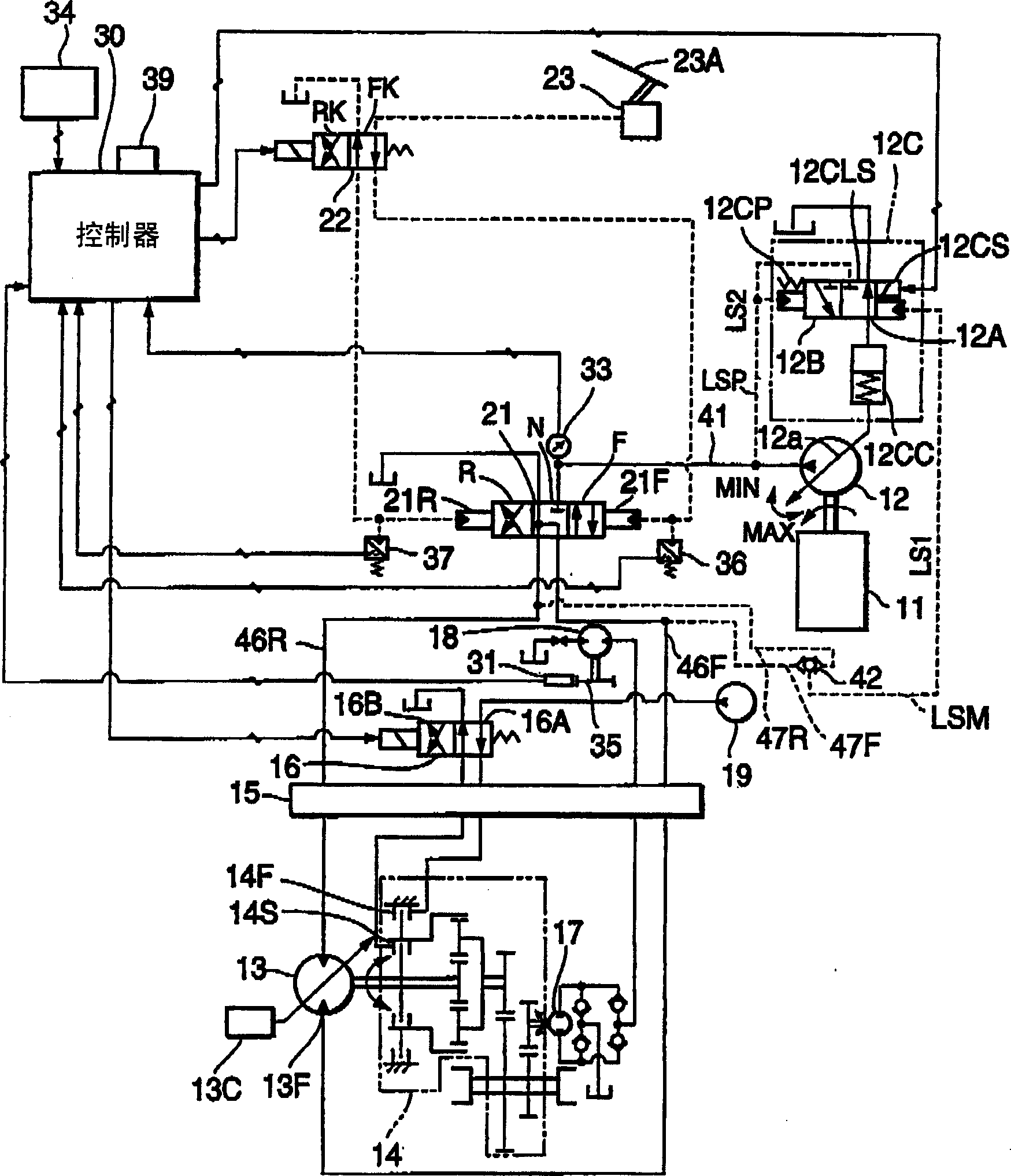
[0010] refer to figure 1 The vehicle speed limiting system of the present invention will be described in detail.

[0011] A travel pump 12 is connected to the engine 11, and the travel pump 12 is driven by the engine 11 to discharge pressure oil. Pressurized oil discharged from the travel pump 12 is sent to the travel motor 13 through the travel control valve 21 and the hydraulic rotary joint 15 . The travel motor 13 is connected to the input shaft of the gearbox 14 to drive the gearbox 14 .

[0012] The transmission 14 is provided with a travel speed detection pump 17 that rotates in proportion to the rotation of the output shaft of the transmission 14 . The pressure oil discharged from the travel speed detection pump 17 is sent to the travel speed detection motor 18 through the oil pressure rotary joint 15 . The travel pump 12 is a variable hydraulic pump and has a pump displacement control mechanism 12C. In addition, the travel motor 13 is a variable hydraulic motor and...


PUM


Abstract

The hydraulic vehicle speed limiter has a pump capacity control (12C) for controlling the pump capacity so that a pressure difference between a load pressure of the travelling hydraulic motor (18) and discharge pressure of the variable capacity pump (17) becomes a load sensing set pressure. A controller (30) changes the set pressure if the detected vehicle speed is above a set value.

Description

technical field [0001] The invention relates to a vehicle speed limiting system for a hydraulically driven vehicle. Background technique [0002] Conventionally, a hydraulic traveling vehicle traveling by driving a variable displacement hydraulic traveling hydraulic motor using pressure oil from a traveling hydraulic pump driven by an engine has a maximum speed limited by the capacity of the traveling hydraulic pump. Furthermore, the maximum vehicle speed varies depending on the country where the hydraulically driven vehicle travels. When exporting a hydraulically driven vehicle to a country with a different maximum vehicle speed, by exporting a vehicle equipped with a traveling hydraulic pump with a different capacity to a different country, to correspond. [0003] However, if various types of hydraulic pumps for traveling are prepared in accordance with the maximum speed of each country in accordance with the maximum speed of the hydraulic traveling vehicle, the types of ...

Claims


Application Information

Patent Timeline
IPC IPC(8): F16H47/04F16H59/44F16H61/46F16H61/47F16H61/66
CPCF16H2059/6861F16H61/46F16H47/04F16H59/44B60W2720/10F16H61/47F16H61/42
Inventor 源司雅明埃里克·雅克
Owner KOMATSU LTD
Features
  • R&D
  • Intellectual Property
  • Life Sciences
  • Materials
  • Tech Scout
  • Unparalleled Data Quality
  • Higher Quality Content
  • 60% Fewer Hallucinations
Learn More