Optical signal transmitting-receiving module and light path controlling method thereof

A technology of a transceiver module and a control method, which is applied in the field of optical signal transceiver modules and their optical path control, and can solve problems such as increased cost, difficult assembly, and large space

Inactive Publication Date: 2004-07-07
DELTA ELECTRONICS INC
View PDF0 Cites 4 Cited by
  • Summary
  • Abstract
  • Description
  • Claims
  • Application Information

AI Technical Summary

Problems solved by technology

[0003] As can be seen from the above, the known design uses the receiver 13 and the transmitter 14 to perform receiving and transmitting operations respectively, and divides the circuit board into two blocks to prevent cross talk and improve transmission efficiency. quality; but the receiving and transmitting ac...

Method used


Image

  • Optical signal transmitting-receiving module and light path controlling method thereof
  • Optical signal transmitting-receiving module and light path controlling method thereof
  • Optical signal transmitting-receiving module and light path controlling method thereof

Examples


Embodiment Construction

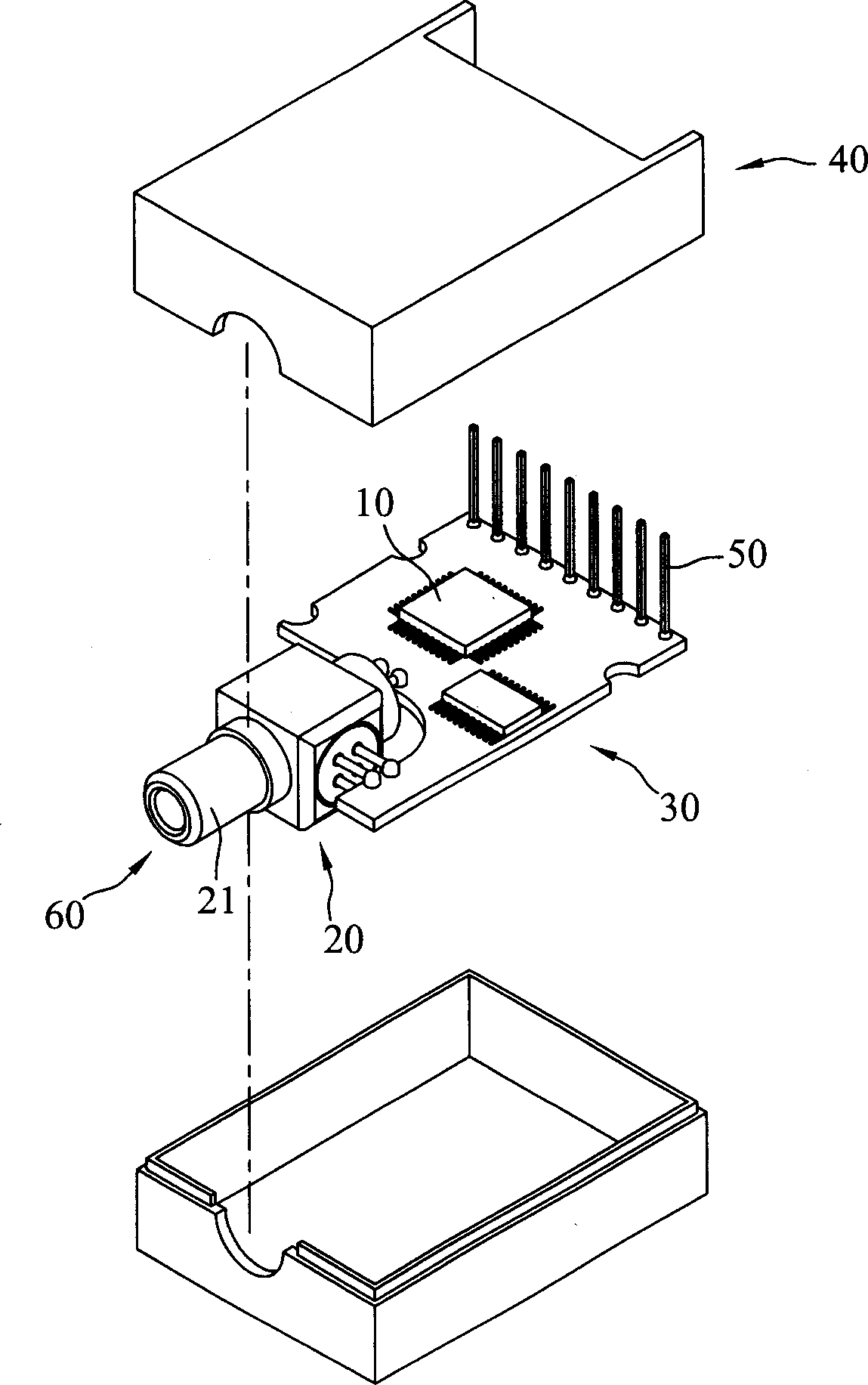
[0034] According to an optical signal transceiver module and its optical path control method according to the present invention, the optical signal transceiver module mainly includes an optical signal transceiver component and a circuit board. Please refer to figure 2 , is a three-dimensional schematic diagram of the optical signal transceiver module of the present invention, the optical signal transceiver module mainly includes an optical signal transceiver component 20 and a circuit board 30, and a plurality of electronic components 10 are arranged on one side of the circuit board 30 for processing the optical signal transceiver component The output and input electrical signals of 20 are connected with the electronic device through the pin 50 . In addition, in order to protect the electronic components 10 on the circuit board 30 and the adjacent optical signal transceiver components 20, a housing 40 is used to cover them to prevent the entry of dust and impurities from the ...


PUM


Abstract

The present invention mainly comprises light signal transceiving component and circuit board. The optical fibre connection end disposed via one side of the light signal transceiving component is connected with optical fibre, a filtering plate is utilized to generate deffection for light signal issued by the optical fibre for it being into input end then the light signal is converted to be electric signal transmitted to the circuit board through photoelectric converting unit. With the same principle as above, the electric signal can be converted to be the light signal which is transmitted to the optical fibre so action of transmitting and receiving light signal can be selected at the same time by setting on optical fibre at an optical connection end.

Description

technical field [0001] The invention relates to an optical signal transceiver module and an optical path control method thereof, which are applied to receive and transmit optical signals, in particular to an optical signal transceiver module integrating output and input optical signals and an optical path control method thereof. Background technique [0002] The prosperity of the optoelectronic industry in recent years has improved the quality of life of the general public. The application of optical fiber networks and the development of leisure home appliances are attributed to the efforts of related research units and industries in optoelectronic communication. Among them, the conversion and transmission of light energy signal and electronic signal play a pivotal role. The optical transceiver module is installed in the electronic device, so that the electronic device can receive or transmit optical signal through optical fiber. Please refer to figure 1 , is a perspective ...

Claims


Application Information

Patent Timeline
IPC IPC(8): G02B6/42H04B10/43
Inventor 徐雨弘林祐年
Owner DELTA ELECTRONICS INC
Why Eureka
Try Eureka