Wireless general module circuit for smart home
A general-purpose module and smart home technology, applied in the direction of data exchange, electrical components, transmission systems, etc. through path configuration, can solve the problems of inconvenient link communication and control, and achieve standardization of hardware solutions, cost reduction, and good stability Effect
- Summary
- Abstract
- Description
- Claims
- Application Information
AI Technical Summary
Problems solved by technology
Method used
Image
Examples
Embodiment 1
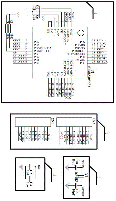
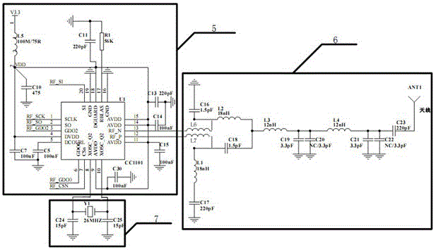
[0023] Such as Figure 1-2 As shown, a smart home wireless general module circuit, the smart home wireless general module circuit includes an MCU main control chip 1 and an external I / O input and output control circuit 2 and a clock oscillation circuit 3 respectively connected to the MCU main control chip 1 , a power filter circuit 4 and an RF transceiver chip circuit 5, the RF transceiver chip circuit 5 is respectively connected with a high-frequency resonant transceiver matching output circuit 6 and a fundamental frequency oscillation circuit 7.
[0024] In the specific implementation process, the MCU main control chip 1 adopts the STM8S103K32 chip U2, its pin 1 is grounded through the capacitor C4, and the pin 1 is also connected to the network NRST; the pin 2 and the pin 3 are connected to the clock oscillation circuit 2; Pin 4 is grounded; pin 5 is grounded through C6; pin 6 is connected to V3.3 power supply; pins 9~20, pins 26 and pins 28~31 are connected to external I / O...
PUM
 Abstract
Description
Claims
Application Information
 - R&D
- Intellectual Property
- Life Sciences
- Materials
- Tech Scout
- Unparalleled Data Quality
- Higher Quality Content
- 60% Fewer Hallucinations
Browse by: Latest US Patents, China's latest patents, Technical Efficacy Thesaurus, Application Domain, Technology Topic, Popular Technical Reports.
© 2025 PatSnap. All rights reserved.Legal|Privacy policy|Modern Slavery Act Transparency Statement|Sitemap|About US| Contact US: help@patsnap.com


