Sealed type electrically driven compressor

An electric compressor, airtight technology, applied in the direction of machines/engines, mechanical equipment, liquid variable capacity machinery, etc., can solve the problems of poor assembly workability, high cost, and complexity, and achieve improved assembly performance, less bending, and restraint The effect of oil sliding

Inactive Publication Date: 2004-07-14
PANASONIC APPLIANCES REFRIGERATION DEVICES SINGAPORE
View PDF2 Cites 24 Cited by
  • Summary
  • Abstract
  • Description
  • Claims
  • Application Information

AI Technical Summary

Problems solved by technology

Although it is a highly reliable method from the viewpoint of ensuring the amount of oil supplied in the low-speed range (1200r / min to 1800r / min), the structure is very complicated and the number of parts is lower than that of the centrifugal force oil pump method. There are many, so the cost is high, and it has the disadvantages of poor assembly workability

Method used


Image

  • Sealed type electrically driven compressor
  • Sealed type electrically driven compressor
  • Sealed type electrically driven compressor

Examples


Embodiment 1

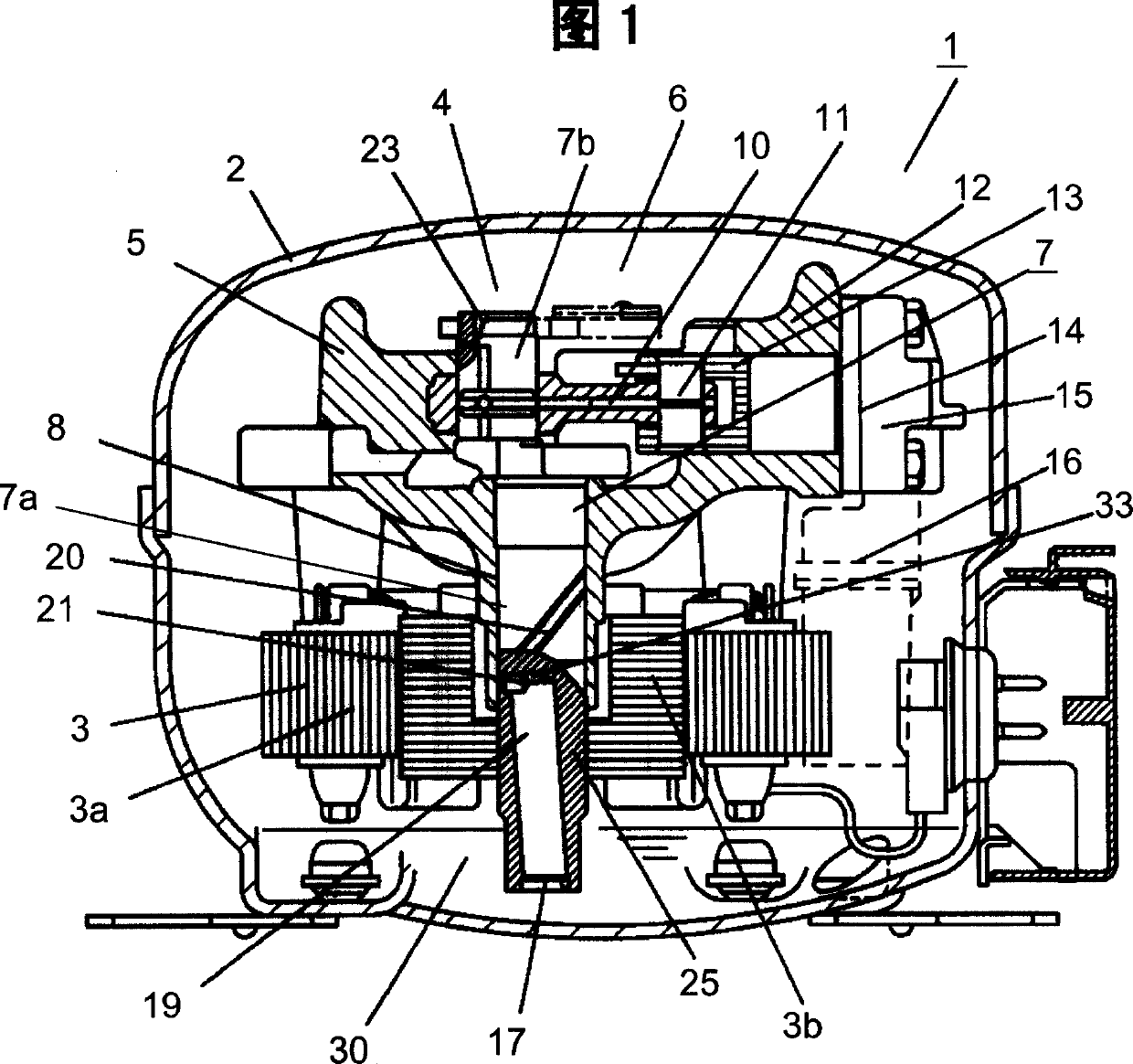
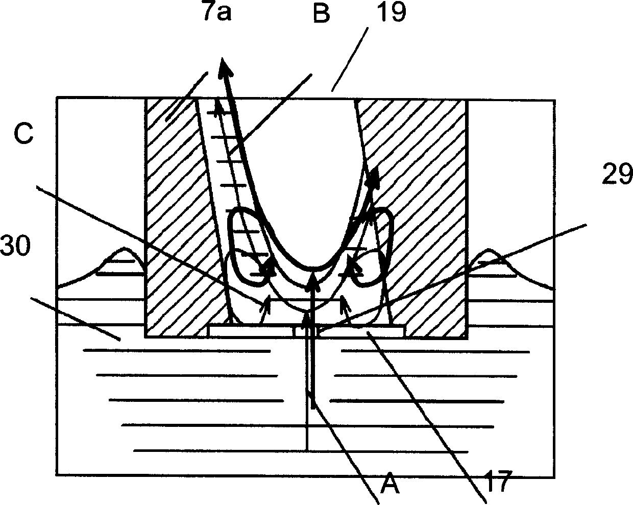
[0043] Fig. 1 is a cross-sectional view of a hermetic electric compressor according to Embodiment 1 of the present invention, Fig. 2 is a cross-sectional view of main parts of a crankshaft according to Embodiment 1, and Fig. 3 is a cross-sectional view of main parts showing the lubricating oil suction action of Embodiment 1 .

[0044] The structure of the hermetic electric compressor body 1 is that an electric motor 3 composed of a stator 3a and a rotor 3b and a compressor unit 6 integrating a compression mechanism 4 and a cylinder 5 are accommodated in an upper and lower airtight container 2 . The crankshaft main shaft part 7a of the crankshaft 7 is supported by the bearing part 8 of the cylinder block 5, and the connecting rod 10 is connected to the upper crankshaft eccentric shaft part 7b, and is connected to the piston 13 sliding in the cylinder 12 through the piston pin 11. The valve plate 14 has a suction hole, a suction valve, a discharge hole, and a discharge valve (no...

Embodiment 2

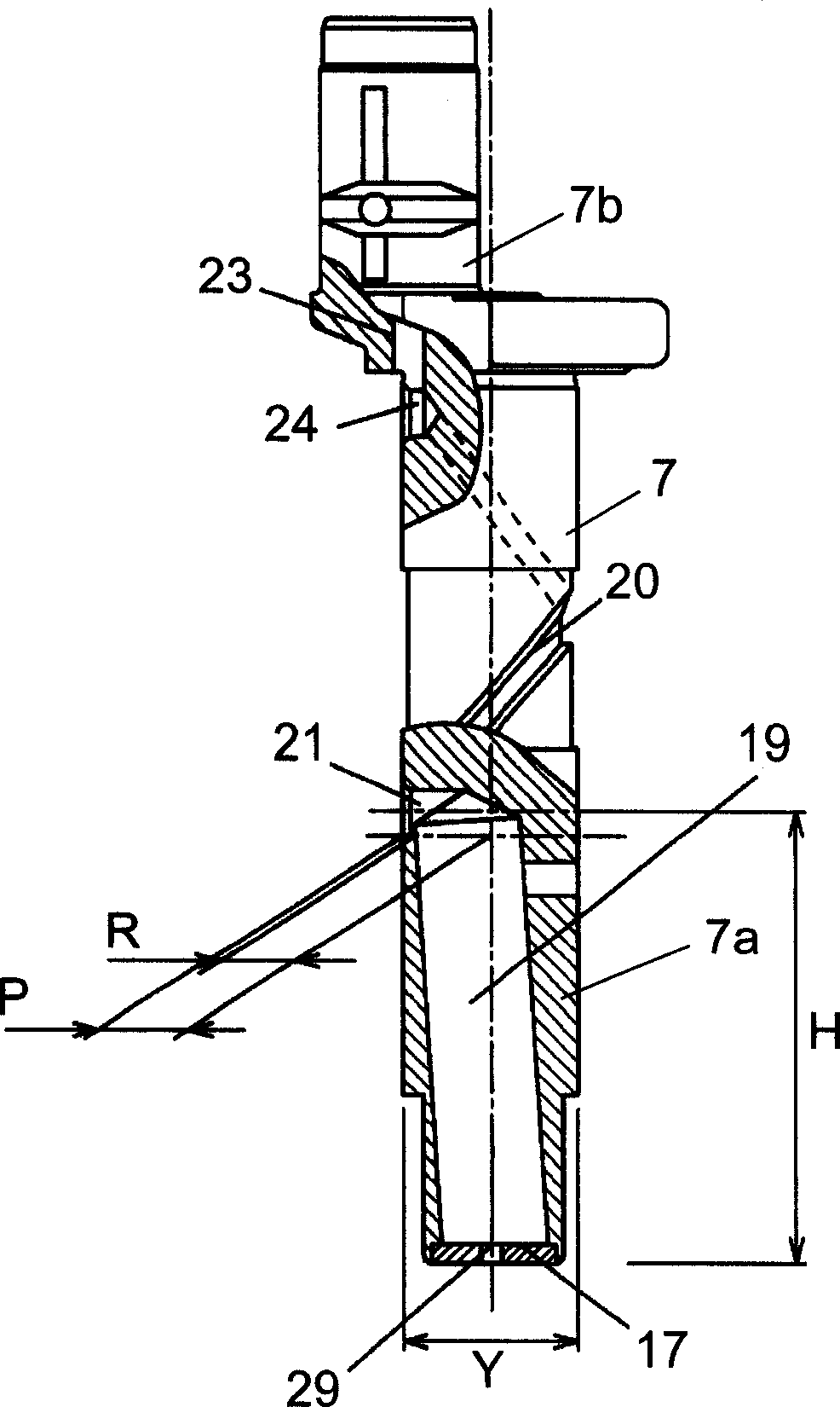
[0063] Fig. 7 is an enlarged cross-sectional view of the lower part of the main shaft portion of the crankshaft according to Embodiment 2 of the present invention.

[0064] As shown in FIG. 7 , an expanded portion 18 and a reduced diameter portion 17 are formed at the lower end portion of the crankshaft main shaft portion 7 a. The inclined passage 19 which becomes the passage of lubricating oil from the upper end of the expanded pipe part 18 is perforated so that it may incline with respect to the axial center of the crankshaft main shaft part 7a. Also, the diameter of the inner peripheral portion of the expanded pipe portion 18 is formed larger than the diameter of the inclined passage 19 . A flat disc-shaped cover member 31 formed by punching a general steel material and having a suction hole 29 for sucking lubricating oil 30 in the center is inserted into and fixed to the inner peripheral surface of the expanded pipe portion 18 . The reduced diameter portion 17 is a generi...

Embodiment 3

[0073] 9 is an enlarged cross-sectional view of the lower part of the crankshaft main shaft according to Embodiment 3 of the present invention. FIG. 10 is a perspective view of the divider, and FIG. 11 is an enlarged cross-sectional view of part D in FIG. 9 .

[0074] The expanded pipe portion 18 is formed at the lower end of the crankshaft main shaft portion 7a. The inclined passage 19 is a lubricating oil passage formed from the upper end of the expanded pipe 18, and the center of the expanded pipe 18 is included in the inner diameter thereof. The divider 26 is a thin plate-like member that is pressed into and fixed in the inclined passage 19, and has substantially half-moon-shaped notches 27 at the upper and lower ends, and is formed vertically symmetrically so that there is no vertical direction. On the divider 26, there is a press-fit portion 28 slightly widened approximately in the middle. In addition, the inclined passage 19 has more than two stages of steps, and its ...


PUM


Abstract

A sealed type electrically driven compressor that efficiently pumps up a necessary amount of lubricating oil even during low speed rotation and achieves good assembling workability by a simple construction. It is provided with an oil pump comprising an inclined passageway formed in the lower portion of a main shaft and inclined outward from below to above, a choke having a suction hole in the center that is smaller in cross section than the inclined passageway formed in the lower end of the main shaft, and a lower communicating section establishing communication between the lower end of a spiral groove and the inclined passageway, whereby the lift for the lubricating oil can be effectively increased.

Description

technical field [0001] The invention relates to a hermetic electric compressor used in a freezing and refrigerating device or an indoor air conditioner. More specifically, it relates to an oil supply and lubrication system for supplying lubricating oil stored in an airtight container to a rotary sliding part in a hermetic electric compressor by utilizing the centrifugal force generated by the rotation of a crankshaft. Background technique [0002] In recent years, there has been a strong demand for low power consumption and quietness in hermetic electric compressors used in household refrigerators and room air conditioners. In order to achieve low power consumption and quietness, the low-speed rotation of the compressor driven by the inverter (for example, about 1800 r / min in the case of a household refrigerator) has been further developed. [0003] In addition, the lubricating oil pump system of the hermetic electric compressor often utilizes the centrifugal force generate...

Claims


Application Information

Patent Timeline
Patent Type & Authority Applications(China)
IPC IPC(8): F04B39/00F04B39/02
CPCF04B39/0253F04B39/0246F04B39/0261F04B39/02
Inventor 石田贵规太田年彦井出照正片山诚堀口隆文长尾崇秀
Owner PANASONIC APPLIANCES REFRIGERATION DEVICES SINGAPORE
Why Eureka
Try Eureka