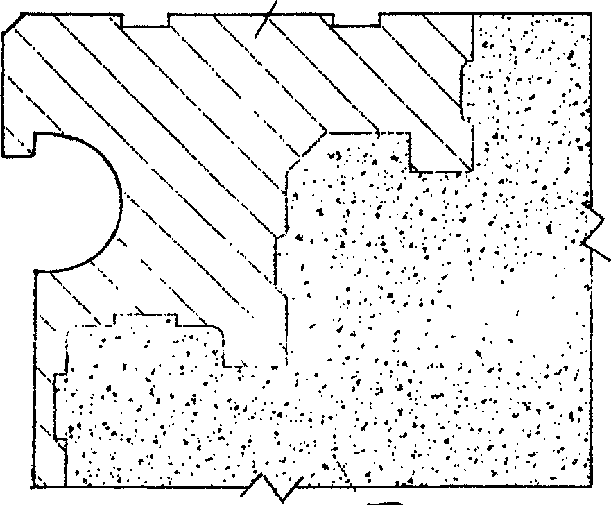
Aluminium alloy bridge expansion and cotraction device and its manufacturing method
A technology of a telescopic device and a manufacturing method, which is applied to bridges, bridge parts, bridge construction, etc., can solve the problems of poor anti-corrosion performance, complicated installation and construction, and long period, and achieve the effects of small structure width, rapid construction, and easy installation and construction.
- Summary
- Abstract
- Description
- Claims
- Application Information
AI Technical Summary
Problems solved by technology
Method used
Image
Examples
Embodiment 1
[0037] According to attached figure 1 , an aluminum alloy bridge telescopic device with a stretching amount of 80mm, the total width is 320mm, the structural height is 65mm, the height of the aluminum alloy side beam 1 is 62mm, and the two aluminum alloy side beams 1 are respectively installed on the telescopic ditch beam body At the position of the beam body where the gap is reserved, epoxy concrete 3 is poured in the transition section between the side beam and the bridge asphalt surface layer 5. Since the joint surface of the side beam 1 and the epoxy concrete 3 is designed to have a concave-convex cross-sectional structure, the epoxy concrete 3 The concrete is embedded in the cross-sectional structure of the side beams to form a great bonding force, so that they cannot move in three-dimensional directions up and down, left and right, and front and back. This reasonable concave-convex structural section does not depend on the size, but on the Depending on the available bond...
Embodiment 2
[0039] According to attached image 3 The two aluminum alloy side beams 1 are respectively installed on the positions of the beam body at the reserved gap of the expansion ditch beam body, and the transition section between the side beam and the bridge asphalt surface layer 5 is poured with rapid high-strength concrete 3, and the beam end where the telescopic device is installed needs to be Pre-embedded anchor bolts 7 are set, and the anchor bolts 7 are used to fix and connect the aluminum alloy anchor plate 6 with the wedge groove. The connection between the high-strength concrete and the aluminum alloy edge beam not only depends on the concave-convex structural section of the joint surface, but also relies on the whole of the wedge groove aluminum alloy anchor plate, so the mutual bonding force is increased. The shape of the expansion groove and the grade of the aluminum alloy material are the same as in Example 1.
Embodiment 3
[0041] According to attached Figure 4 Two aluminum alloy side beams 1 are respectively installed on the positions of the beam body at the reserved gap of the expansion ditch beam body, and the transition section between the side beam and the bridge asphalt surface layer 5 is poured with high-strength concrete 3, and steel fibers 8 are mixed into the concrete, The end of the beam where the telescopic device is installed needs to be pre-embedded and bent into a "冂"-shaped steel bar 9. After one end of the anchor bolt 7 is threaded with the aluminum alloy side beam on the concrete joint surface, the anchor bolt is welded to the pre-embedded "" when the other end is installed. 冂”-shaped steel bar 9, so that the connection between the aluminum alloy edge beam and the concrete depends on the concave-convex structural section of the joint surface on the one hand, and on the other hand relies on the anchor bolt 7 and the pre-embedded steel bar 9 to increase the bonding force and attach...
PUM
| Property | Measurement | Unit |
|---|---|---|
| flexibility | aaaaa | aaaaa |
Abstract
Description
Claims
Application Information
 - R&D
- Intellectual Property
- Life Sciences
- Materials
- Tech Scout
- Unparalleled Data Quality
- Higher Quality Content
- 60% Fewer Hallucinations
Browse by: Latest US Patents, China's latest patents, Technical Efficacy Thesaurus, Application Domain, Technology Topic, Popular Technical Reports.
© 2025 PatSnap. All rights reserved.Legal|Privacy policy|Modern Slavery Act Transparency Statement|Sitemap|About US| Contact US: help@patsnap.com


