Structure for installing a rear cushion
A rear buffer and buffer technology, applied in the field of hydraulic shock absorbers, to achieve the effect of reducing weight, reducing cost and high installation rigidity
- Summary
- Abstract
- Description
- Claims
- Application Information
AI Technical Summary
Problems solved by technology
Method used
Image
Examples
Embodiment Construction
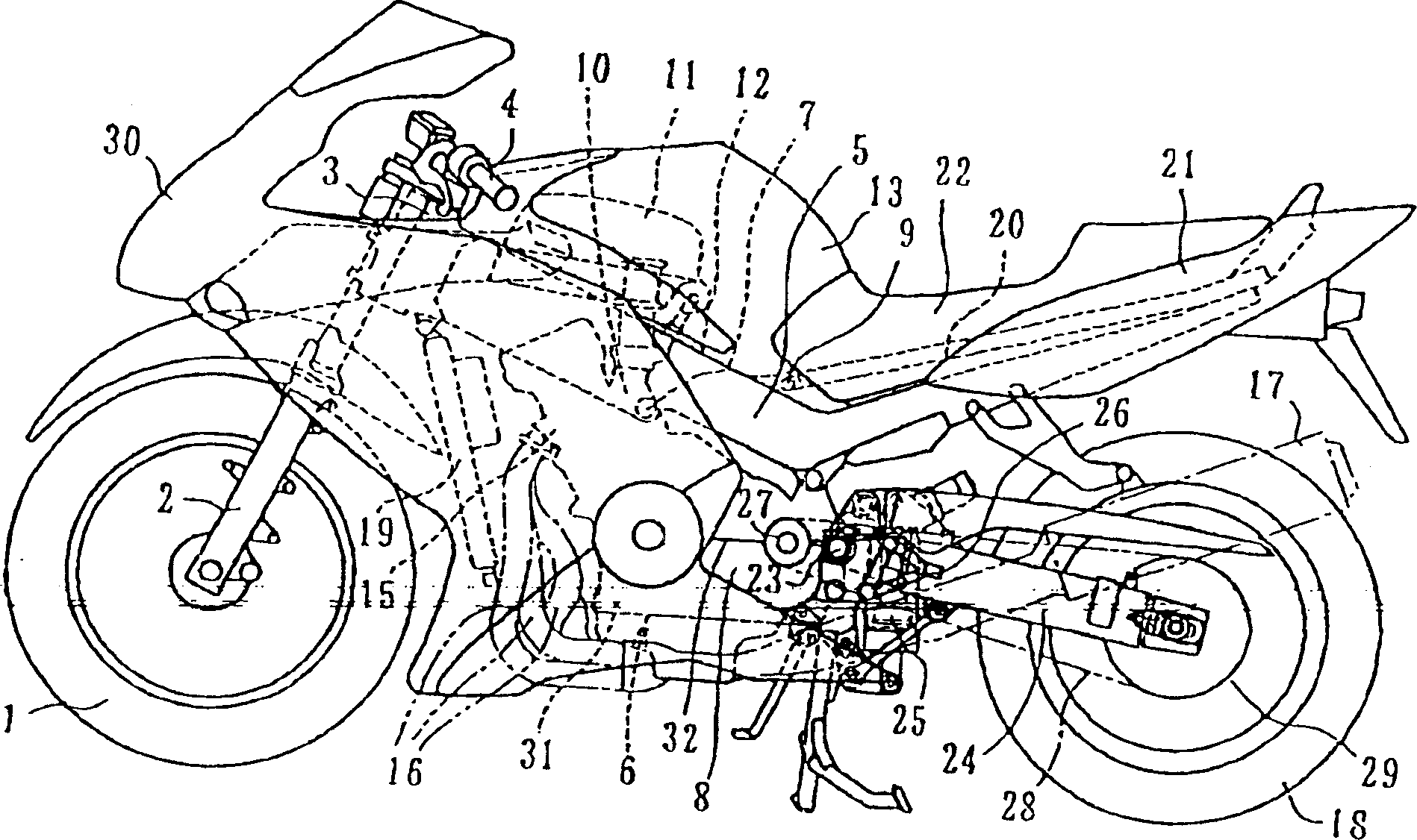
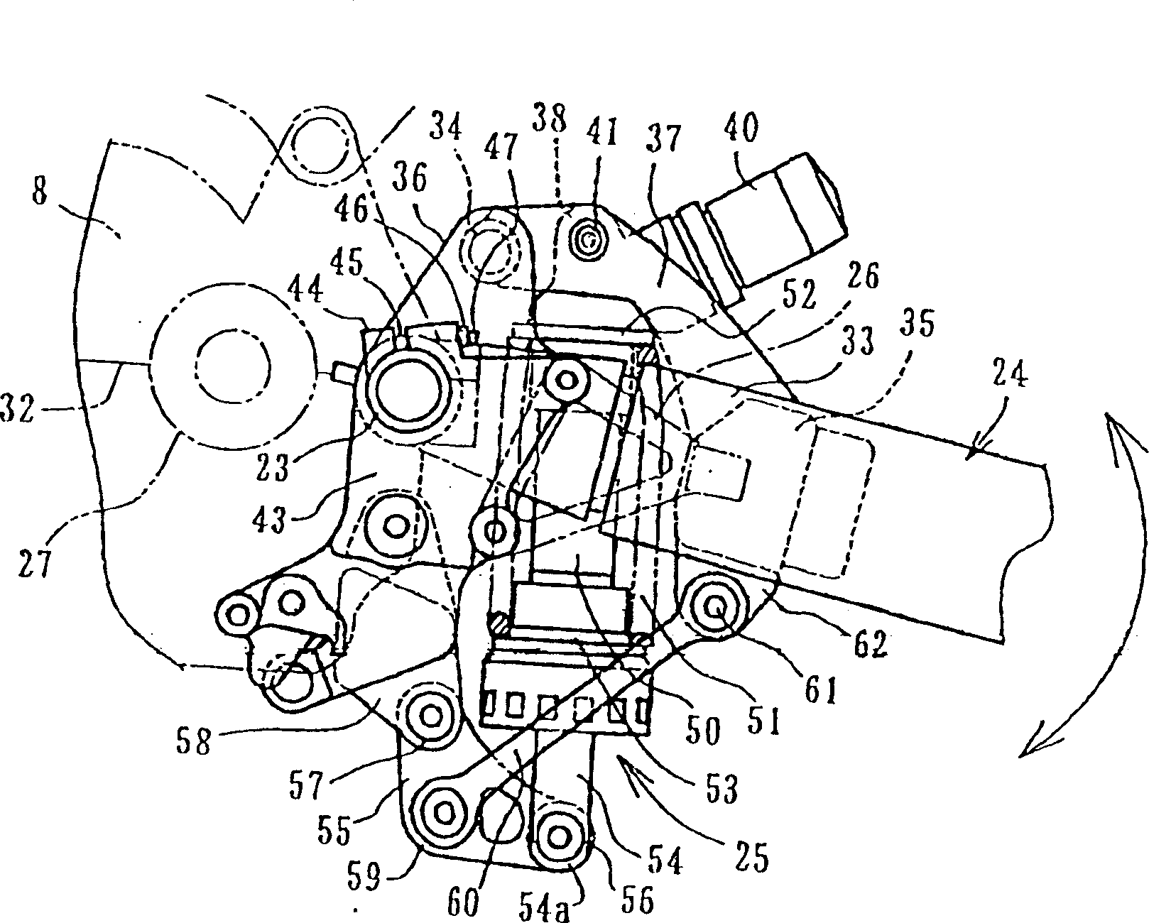
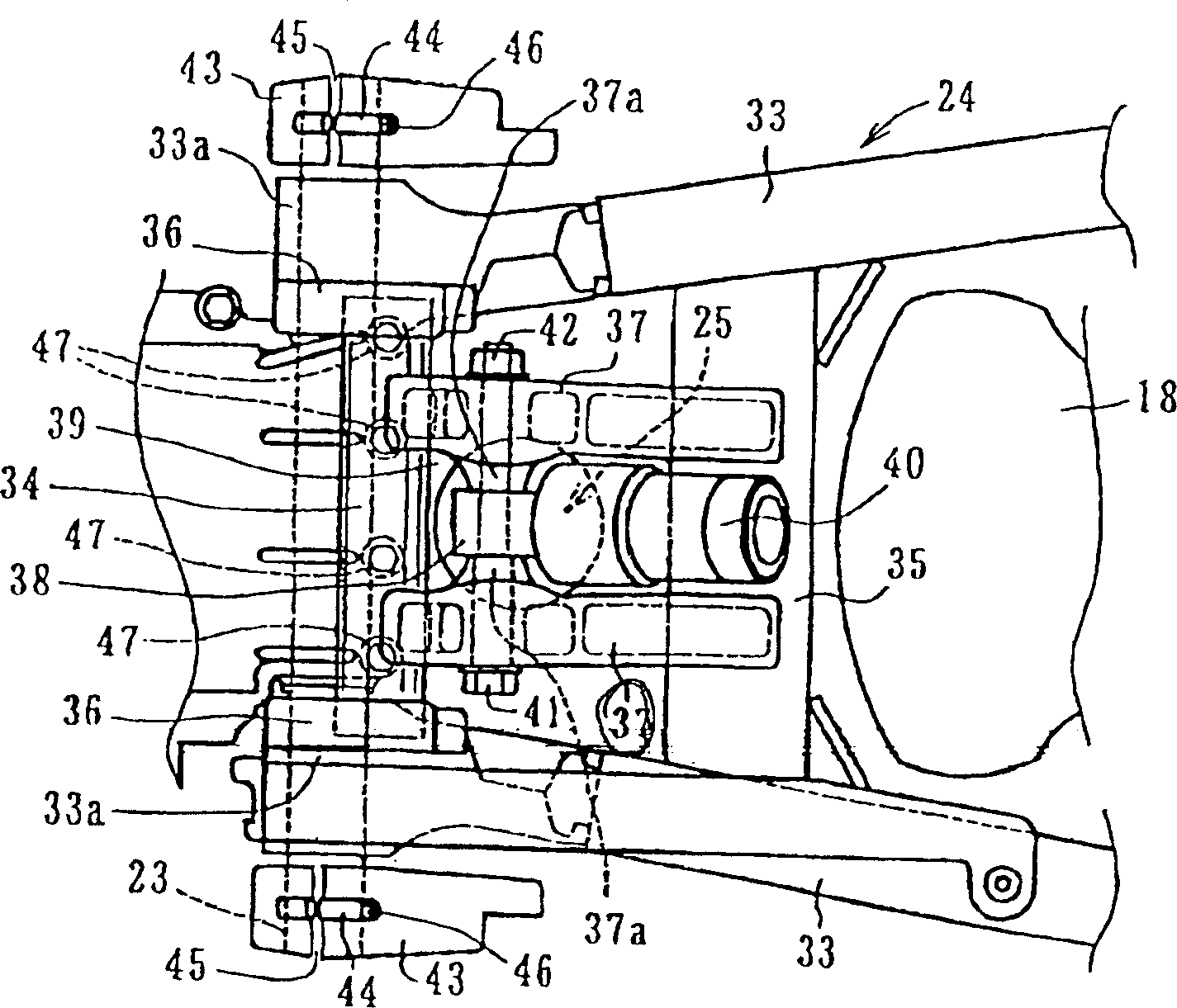
[0032] Figures 1 to 4 An example is shown in which the present invention is applied to a rear swing arm of a type supported at both ends, figure 1 is a side view showing the motorcycle according to the present embodiment; figure 2 is a side view showing the rear suspension portion; image 3 is its top view; Figure 4 is a sectional view showing a link mechanism.
[0033] figure 1 A wheel 1 , a front fork 2 , a head pipe 3 , a handlebar 4 , and a main frame 5 are shown in FIG. The main frame 5 is in the shape of a longitudinal square column, made of light alloy, bifurcated from the head pipe into left and right parts, inclined and extending downward and rearward.
[0034] Below the main frame 5, a row of four-cylinder engines 6 is supported. There are two support points: a support point 7 between the middle part of the main frame 5 and the upper part of said cylinder; and a gearbox 8 between the rear end of the main frame 5 and for constituting the engine 6 at its rear ...
PUM
 Abstract
Description
Claims
Application Information
 - R&D
- Intellectual Property
- Life Sciences
- Materials
- Tech Scout
- Unparalleled Data Quality
- Higher Quality Content
- 60% Fewer Hallucinations
Browse by: Latest US Patents, China's latest patents, Technical Efficacy Thesaurus, Application Domain, Technology Topic, Popular Technical Reports.
© 2025 PatSnap. All rights reserved.Legal|Privacy policy|Modern Slavery Act Transparency Statement|Sitemap|About US| Contact US: help@patsnap.com


