Gas apray generating apparatus

A technology for generating devices and aerosols, which is used in spray devices, liquid spray devices, maintenance and safety accessories, etc., and can solve problems such as the inability to apply the minimum amount and the difficulty of increasing the diameter of the oil hole.

Inactive Publication Date: 2004-09-01
EBARA CORP
View PDF0 Cites 14 Cited by
  • Summary
  • Abstract
  • Description
  • Claims
  • Application Information

AI Technical Summary

Problems solved by technology

[0014] For example, the outlet diameter of the nozzle or the oil hole diameter of the tool can be increased to reduce the resistance of the conveying flow channel. In this case, there is no problem. However, for tools with small outer diameters such as small diameter drill bits, there are size constraints. , so it is difficult to increase the oil hole diameter
Therefore, minimum quantity lubrication (MQL) machining cannot be applied to small-diameter drills and the like in many cases

Method used


Image

  • Gas apray generating apparatus
  • Gas apray generating apparatus
  • Gas apray generating apparatus

Examples


Embodiment Construction

[0058] Hereinafter, embodiments of the present invention will be described with reference to the drawings.

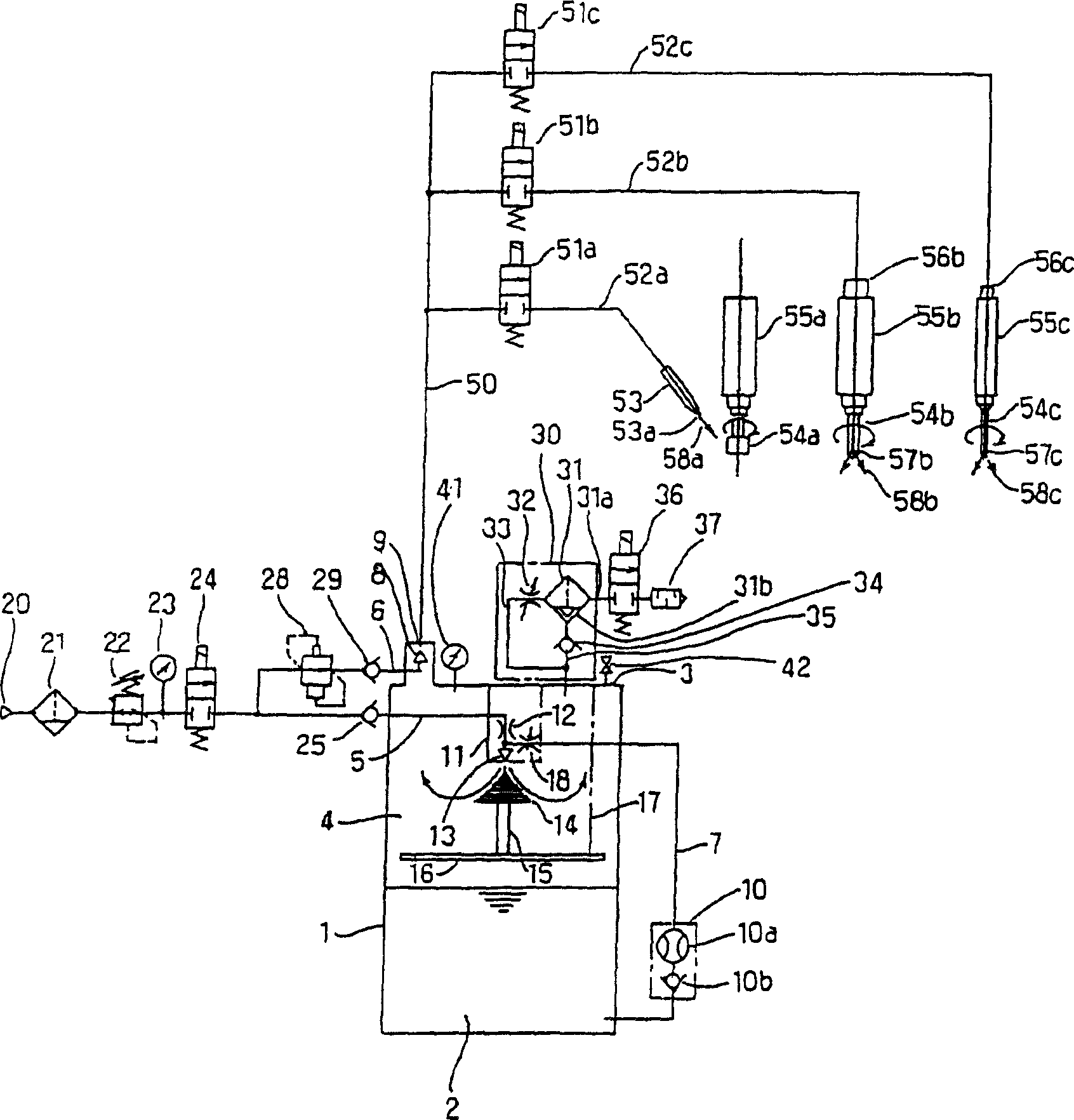
[0059] figure 1 Shown is the schematic structure of the gas mist generating device according to the first embodiment of the present invention. This aerosol generating device includes a container 1 in which a liquid supply source (oil source) 2 for supplying a liquid cooling lubricant such as oil, for example, is accommodated in a lower portion thereof. The container 1 constitutes a pressure container covered by a lid 3. In the space 4 of the container 1 formed above the oil source 2, the ejector 11 is fixedly installed on the cover 3 and receives the supply of pressurized air (gas) and oil (liquid), and the mist ejected from the ejector 11 stays In space 4. The supply of pressurized air (gas) from the ejector 11 is performed through the gas supply passage 5. When the pressurized air passes through the throttle 12 provided in the ejector 11, the cross-sectional area increa...


PUM


Abstract

A mist generator is provided to avoid pressure adjustment in carrier gas supply to a carrier gas jet and to make MQL(Minimum Quantity Lubricant) processing possible. A mist generator comprises an injector(11) generating mist by receiving the liquid in a container(1) and the gas from a gas supply resource(20) and injecting the mist into the container, a duct(9) taking the mist in the container out of the container, and a carrier gas jet(8) communicated with the duct. A first pressure control unit(22) is installed in a gas supply passage(5) for supplying gas to the injector from the gas supply resource. A second pressure control unit(28) installed in a carrier gas supply passage(6) controls the secondary pressure of the first pressure control unit at a specific rate.

Description

Technical field [0001] The present invention relates to an aerosol generating device, which supplies gas and liquid to generate aerosol in a container, transports the generated aerosol through a conveying channel, and sprays the generated aerosol to a target object, and particularly relates to a cooling and lubricating machine tool processing center ( machining center), lathes and other working machinery tools or the aerosol of the processed objects. Background technique [0002] Aerosols (liquid particles contained in gas) are widely used in various technical fields such as inhalers in the medical field, humidifiers in the field of daily life, applications in washing, and coating agents. In addition, the aerosol is also used for cooling and lubricating the tools of the working machine or the processed objects. [0003] For example, in mechanical processing, there is a relatively large frictional force between processing and between the tool and the processed object, and a large ...

Claims


Application Information

Patent Timeline
Patent Type & Authority Applications(China)
IPC IPC(8): B23Q11/10B05B7/04B05B7/26B23Q11/00
CPCY02P70/10B05B7/2494F16N7/34
Inventor 泷川胜大野隆史
Owner EBARA CORP
Why Eureka
Try Eureka