Descending naphtholite catalytic cracking method

A catalytic conversion method and hydrocarbon oil technology, which is applied in the field of downlink catalytic cracking of hydrocarbon oil, can solve the problems of insufficient conversion capacity of heavy oil catalysts, insufficient conversion capacity of heavy oil, and excessive cracking of products, so as to improve activity and selectivity of light products , good macromolecule cracking ability, and the effect of improving heavy oil conversion ability

Inactive Publication Date: 2004-09-22
CHINA PETROLEUM & CHEM CORP +1
View PDF4 Cites 10 Cited by
  • Summary
  • Abstract
  • Description
  • Claims
  • Application Information

AI Technical Summary

Problems solved by technology

In the down-going reaction section of the invention, since the hydrocarbon oil feedstock is directly injected into the dilute-phase bed in the down-going pipe, the initial contact efficiency of the oil agent is low and the heavy oil conversion capacity is insufficient
If a gas-solid quick separator is installed at the outlet of the downpipe, the product must contain more heavy oil; if no gas-solid quick separator is installed at the outlet of the downpipe, the product generated by the downlink reaction and the unconverted hydrocarbon oil raw material will be together Entering the upward reaction section to continue the reaction, the result will inevitably lead to excessive cracking of some products, which will increase the yield of dry gas and coke
[0014] To sum up, the existing downward reactors have problems of low oil agent contact efficiency, insufficient heavy oil conversion capacity or serious tendency of catalyst back-mixing and equipment coking to varying degrees. So far, the above problems can be properly solved, and the reaction Downward reactor with good performance has not been reported yet
[0015] After repeated research and experiments, we realized that the main reason for the low conversion capacity of heavy oil in the down-flow reactor is the low catalyst density in the initial contact area of ​​the oil agent, generally only 10kg / m 2 s, cannot provide enough active centers for the cracking reaction of hydrocarbon oil feedstock

Method used


Image

  • Descending naphtholite catalytic cracking method
  • Descending naphtholite catalytic cracking method
  • Descending naphtholite catalytic cracking method

Examples


Embodiment 1

[0049] This example illustrates: the test results obtained under conventional catalytic cracking reaction conditions by adopting the method provided by the present invention and its down-flow reactor.

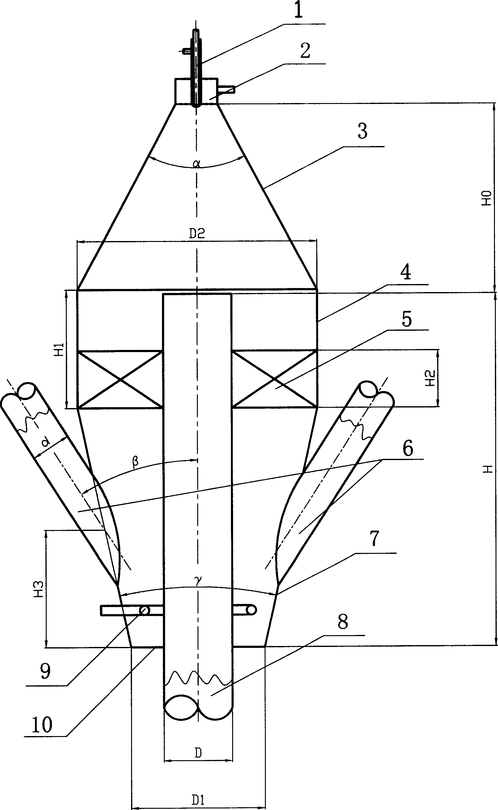
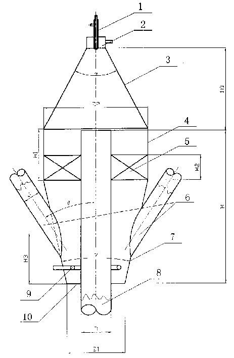
[0050] The inner diameter of the downcomer reactor used in this embodiment is D=20mm; the outer cylinder of the catalyst pre-lifting zone is a straight cylinder with a diameter of D1=2D and a height of 6D; the height difference of the upper end surface of the downcomer to the floor 10 is H=6D; The height difference between the outlet of the nozzle 1 and the upper end surface of the downcomer 8 is H0=2D. The catalyst delivery line 6 is an inclined pipe with a diameter of d=0.8D, which is fixedly connected to the outer cylinder along the direction of the oblique tangent of the outer cylinder 4, and the vertical angle β=30° of its center line, and the outer cylinder The height difference H3 from the body intersection point to the bottom end of the outer cylinder = 2D. Regular pac...

Embodiment 2

[0054] This embodiment illustrates: adopt the method provided by the present invention and its descending type reactor to obtain under harsher reaction conditions test result.

[0055] The structure of the down-flow reactor used in this embodiment is as follows figure 1 As shown, the diameter D=20mm of the downcomer reactor; the lower end diameter D1=2.5D of the lower conical cylinder 7 of the catalyst pre-lift zone, the upper end diameter D2=3.5D, and its height is 3D; the height of the upper straight cylinder 4 H1=2D; the height difference between the inlet of the downcomer and the bottom of the outer cylinder 7 is H=5D; the height difference between the outlet of the nozzle 1 and the inlet of the downcomer 8 is H0=1.5D. The catalyst delivery pipeline 6 is two symmetrically arranged inclined pipes with diameter d=0.7D, the vertical angle β=30° between the center lines, and the height difference h3=2D from the intersection point of the outer cylinder to the bottom of the oute...

Embodiment 3

[0059] This embodiment illustrates: adopt the method provided by the present invention and its descending type reactor to obtain under the reaction condition of high severity test result.

[0060] The structure of the down-flow reactor used in this embodiment is as follows figure 1 As shown, the diameter D=20mm of the downcomer reactor; the lower end diameter D1=2.5D of the lower conical cylinder body 7 of the catalyst pre-lift zone, the upper end diameter D2=4D, and its height is 4D; the height H1 of the upper straight cylinder body 4 =2D; the height difference between the inlet of the downcomer and the bottom of the outer cylinder 7 H=6D; the height difference between the outlet of the nozzle 1 and the inlet of the downcomer 8 H0=iD. The catalyst delivery pipeline 6 is three symmetrically arranged inclined pipes with diameter d=0.7D, the vertical angle β=30° of the center line, and the height difference h3=2D from the intersection point of the outer cylinder to the bottom of...


PUM

PropertyMeasurementUnit
diameteraaaaaaaaaa

Abstract

A down-flow catalytic cracking process for hydrocarbon oil includes such steps as spraying the raw hydrocarbon oil in an reactor by nozzle, atomizing in atomizing chamber, contacting with catalyst, reacting in reaction pipe, quick separating of oil mixture, introducing the oil gas to the followed separation system, and stripping and regenerating the used catalyst for cyclic use. It can increase the conversion power of heavy oil and improve the distribution of products.

Description

technical field [0001] The invention belongs to the catalytic conversion method of petroleum hydrocarbons in the absence of hydrogen, more specifically, it is a downward catalytic cracking method of hydrocarbon oil. Background technique [0002] With the development of the economy, the demand for vehicle fuel and low-carbon olefins based on petroleum will continue to increase around the world. Due to limited oil resources, the development of deep processing of heavy oil and increasing the supply of light oil products and low-carbon olefins will still be a major development strategy for the oil refining industry in the 21st century. Catalytic cracking raw materials have wide adaptability and large conversion depth. While converting heavy raw materials into gasoline, diesel and other vehicle fuels, the liquefied gas generated contains more low-carbon olefins, which is the secondary processing of heavy oil. The most important craft. The catalytic cracking unit has a large sca...

Claims


Application Information

Patent Timeline
Patent Type & Authority Applications(China)
IPC IPC(8): C10G11/00
Inventor 侯栓弟许克家龙军张久顺钟孝湘张占柱何俊武雪峰李松年朱丙田赵俊鹏
Owner CHINA PETROLEUM & CHEM CORP
Why Eureka
Try Eureka