Producing object connecting device and carrying system therewith

A technology for a handover device and a manufacturing device, applied in the field of conveying systems, can solve the problems of inability to process wafers smoothly, reduced wafer production efficiency, surplus production capacity, etc.

Inactive Publication Date: 2004-09-22
SEIKO EPSON CORP
View PDF2 Cites 6 Cited by
  • Summary
  • Abstract
  • Description
  • Claims
  • Application Information

AI Technical Summary

Problems solved by technology

However, if the number of wafers transported by the conveyor belt does not match the number of wafers that can be handled by the manufacturing equipment, the wafers supplied to the manufacturing equipment cannot be processed smoothly.
Therefore, there is a problem that the production capacity is surplus and the production efficiency of the wafer is lowered.

Method used


Image

  • Producing object connecting device and carrying system therewith
  • Producing object connecting device and carrying system therewith
  • Producing object connecting device and carrying system therewith

Examples


Embodiment 1

[0069] Figure 3 ~ Figure 8 Embodiment 1 of the manufacture object delivery apparatus 13 of this invention is shown.

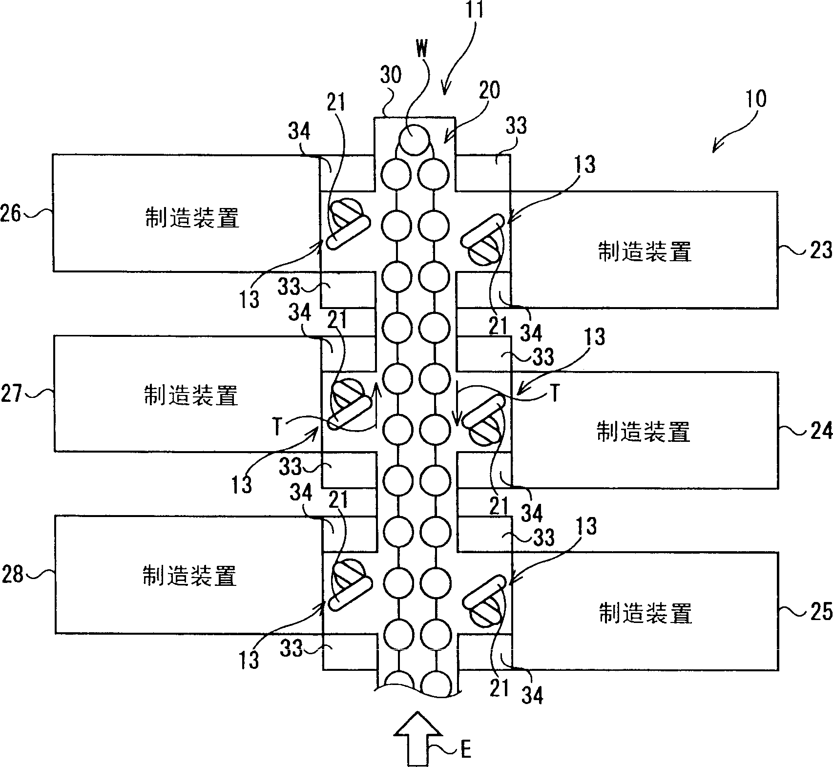
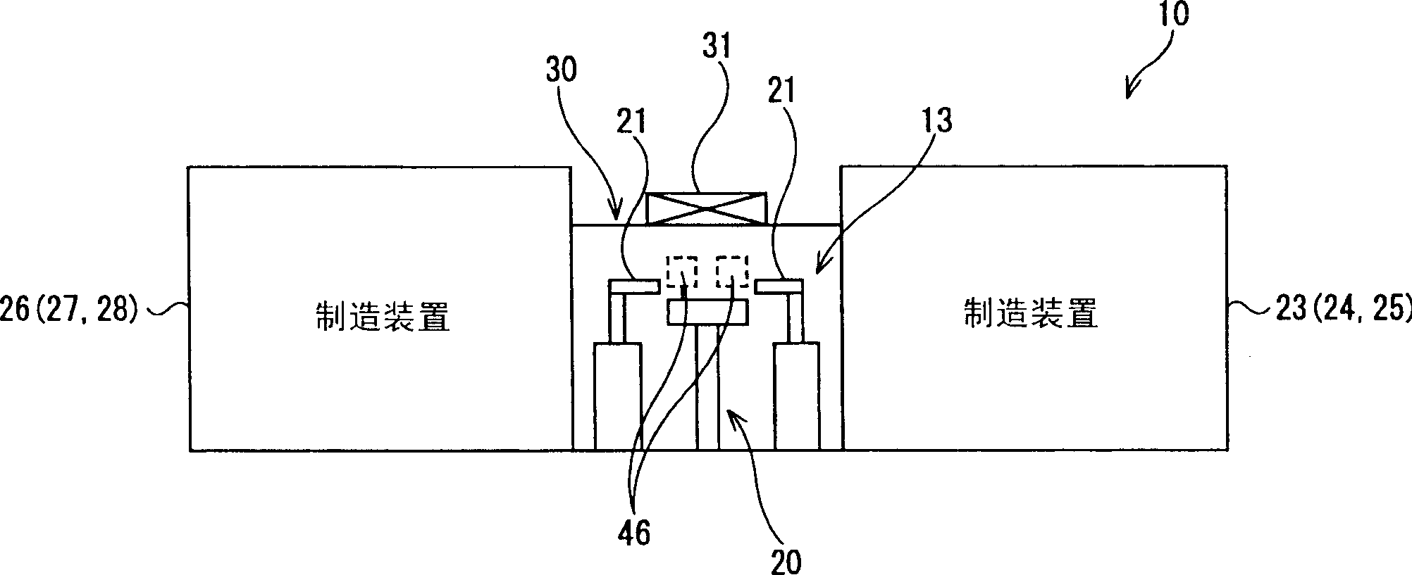
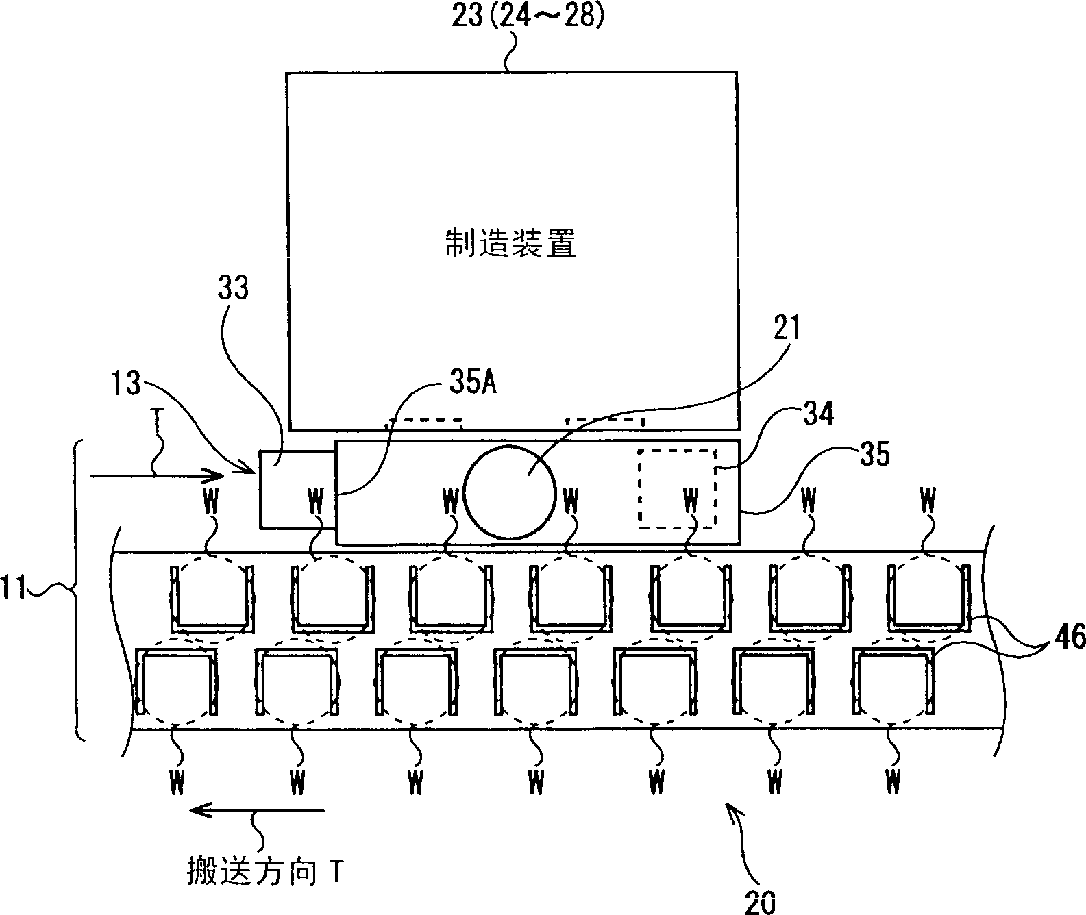
[0070] image 3 It is a plan view representatively showing the manufacturing target delivery device 13 and one manufacturing device 23 . Figure 4 and Figure 5 It is a perspective view representatively showing the manufacturing target delivery device 13 and one manufacturing device 23 .

[0071] exist Figure 3 ~ Figure 5 Among them, the manufacturing target delivery device 13 has a transfer robot 21 , a buffer 34 , a loading port (a type of auxiliary port) 33 , and a main body 35 .

[0072] The main body 35 is disposed between the manufacturing device 23 and the single-sheet conveying conveyor 20 . The main body 35 accommodates the transfer robot 21 and the buffer 34 described above inside.

[0073] The loading port 33 protrudes laterally from one side portion 35A of the main body 35 . The protruding direction of the loading port 33 is parallel to the...

Embodiment 2

[0106] Below, explain Figure 10 ~ Figure 12 Embodiment 2 of the conveyor system of the present invention is shown.

[0107] Figure 10 ~ Figure 12 shown in Example 2 and Figure 3 ~ Figure 5 Compared with the first embodiment shown, the manufacturing apparatus 23 ( 24 to 28 ) and the single-sheet conveying conveyor 20 have the same structure.

[0108] The transfer system 11 has a single sheet transfer conveyor 20 and an object delivery device 13 . Figure 10 ~ Figure 12 The structure of the manufactured object transfer device 13 and Figure 3 ~ Figure 5 The illustrated object delivery device 13 has a different structure.

[0109] Therefore, the manufactured object delivery device 13 will be described. To manufacturing device 23 (24~28) and single piece conveying conveyor belt 20, adopt Figure 3 ~ Figure 5 Description of the manufacturing apparatus 23 (24-28) and the single sheet conveying conveyor 20.

[0110] Figure 10 ~ Figure 12 The manufacturing apparatus 23 sho...

Embodiment 3

[0122] Figure 13 ~ Figure 15 Example 3 of the transport system of the present invention is shown.

[0123] Figure 13 ~ Figure 15 Shown in Example 3 with Figure 10 ~ Figure 12 The same parts as in the illustrated second embodiment are the configurations of the manufacturing device 23 ( 24 to 28 ), the wafer transfer device 61 , and the single-chip transfer conveyor 20 . Figure 13 ~ Figure 15 The structure and Figure 10 ~ Figure 12 The configuration of the manufacturing target delivery device 13 of the illustrated second embodiment is slightly different.

[0124] Therefore, stating Figure 13 ~ Figure 15 The configuration of the manufacturing target delivery device 13 is shown.

[0125] Such as Figure 13 ~ Figure 15 As shown, the manufactured object delivery device 13 has a main body 235 . The main body 235 is rectangular in plan view. On the upper surface of the main body 235, a filter device 38 with a fan is provided. The filter unit 38 with a fan creates an air...


PUM


Abstract

Provided is a system for delivering a production object, e.g. a wafer, quickly and surely between a line for carrying a sheet production object and a production system of the production object, and to provide a carrying system having the delivery system of the production object. The system 13 for delivering a production object W between a line 20 for carrying a sheet production object W and a production system of the production object W comprises a robot 21 for transferring the production object W between the sheet object carrying line 20 and the production system, and a buffer 34 for temporarily storing the production object W transferred from the single object carrying line 20 by means of the transfer robot 21 or the production object W processed by the production system.

Description

technical field [0001] The present invention relates to an object delivery device for delivering an object to be manufactured, such as a semiconductor wafer, and a transfer system having the object delivery device. Background technique [0002] For example, among semiconductor manufacturing apparatuses for manufacturing semiconductor wafers (hereinafter referred to as wafers), there are various wafer manufacturing apparatuses such as photolithography apparatuses, film formation apparatuses, etching apparatuses, cleaning apparatuses, and inspection apparatuses. [0003] In the semiconductor manufacturing process, wafers are moved between these wafer manufacturing devices and processed in each manufacturing device to perform manufacturing. [0004] To move wafers between these wafer processing apparatuses, wafer cassettes are used. Such a wafer cassette is a cassette that detachably accommodates a plurality of wafers. A plurality of wafers are accommodated in the cassette ac...

Claims


Application Information

Patent Timeline
Patent Type & Authority Applications(China)
IPC IPC(8): B65G47/90H01L21/677H01L21/68H01L21/687
CPCH01L21/67778H01L21/67766H01L21/68707H01L21/67769H01L21/67736H01L21/68
Inventor 藤村尚志田中秀治小林义武
Owner SEIKO EPSON CORP
Why Eureka
Try Eureka