Device for distributing granular material onto a continuously travelling support and bunker for granular material

A bulk material and silo technology, which is applied in the pretreatment of molding materials, household components, household appliances, etc., can solve the problems of high investment cost and high cost, achieve high production capacity, reduce the structure height, and save manufacturing costs

Inactive Publication Date: 2004-09-29
DIEFFENBACHER GMBH & CO KG
View PDF1 Cites 8 Cited by
  • Summary
  • Abstract
  • Description
  • Claims
  • Application Information

AI Technical Summary

Problems solved by technology

In addition to the high investment costs for the fiber loosening device itself, additional c

Method used


Image

  • Device for distributing granular material onto a continuously travelling support and bunker for granular material
  • Device for distributing granular material onto a continuously travelling support and bunker for granular material
  • Device for distributing granular material onto a continuously travelling support and bunker for granular material

Examples


Embodiment Construction

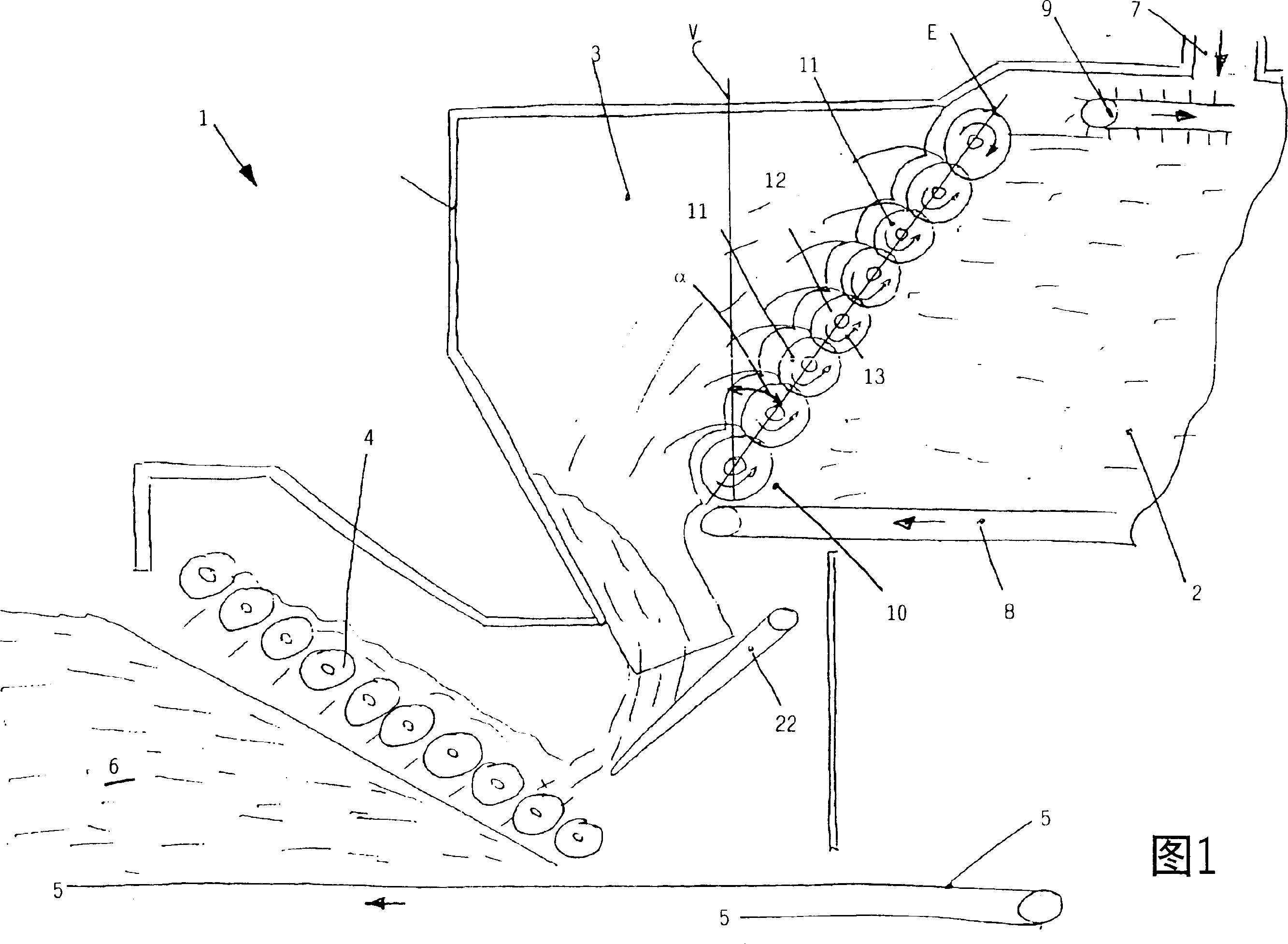
[0031] Figure 1 shows a schematic view of a spreading station 1, which is provided with a dosing bin 2, a stabilizing grid 3, a spreading roller device 4 and a forming belt 5 formed from loose bulk material Material fiber layers (Material vlies) 6 are sprinkled on the forming belt.

[0032] Lignocellulosic and / or cellulose-containing particles of different particle sizes, such as fibers, wood chips and the like, are considered primarily as dispersed bulk material. For the production of fiberboards, wood fibers provided with adhesives are usually used.

[0033] The glued wood fibers are conveyed to the feed area 7 of the metering silo 2 via a screw conveyor, not shown. Through a rotating process, the screw conveyor distributes the fibers over the entire width of the silo. A bottom conveyor belt 8 is provided at the bottom of the silo, on which wood fibers are deposited and the entire fiber layer deposited is slowly transported to an outfeed area 10 . In order to deliver as u...


PUM


Abstract

The scattering apparatus (1) includes a roller arrangement (11) which is arranged in the discharge section (10) of a metering hopper (2). The roller arrangement processes the scattered grits. An Independent claim is also included for a hopper.

Description

technical field [0001] The invention relates to a device for spreading bulk material on a continuously moving base part and a silo for metered discharge of bulk material. Background technique [0002] When producing wood-based panels, in particular wood-fibre panels, there is the problem that the fibers form so-called fiber balls by transport from the refiner to the actual discharge point in the spreading head. This is usually caused by wall friction, backcombing devices, screw conveyors, etc., which cause the material to turn over and coalesce the fibers into spherical fiber aggregates. These fiberballs are highly undesirable since they lead to cloudy surface structures in the finished wood fiberboard and appear as visual quality defects. [0003] Furthermore, in these devices in which the material flow consisting of glued wood particles or fibers moves, sticking and deposits can occur, which are then suddenly dislodged by vibrations or other forces and become entrained in...

Claims


Application Information

Patent Timeline
IPC IPC(8): B27N3/14
CPCB27N3/14
Inventor 格哈德·梅尔策
Owner DIEFFENBACHER GMBH & CO KG
Why Eureka
Try Eureka