Fuel cell system

A fuel cell system and fuel technology, which is applied to fuel cells, circuits, electrical components, etc., can solve the problems such as the unavailability of hydrogen gas and the limitation of power generation efficiency, and achieve the effect of improving energy utilization efficiency, saving fuel, and improving power generation performance.

Inactive Publication Date: 2004-09-29
LG ELECTRONICS (TIANJIN) APPLIANCES CO LTD
View PDF0 Cites 1 Cited by
  • Summary
  • Abstract
  • Description
  • Claims
  • Application Information

AI Technical Summary

Problems solved by technology

[0014] Therefore, the prior art fuel cell having the above-mentioned structure has the following disadvantages: the hydrogen gas produced by the anode si...

Method used


Image

  • Fuel cell system
  • Fuel cell system
  • Fuel cell system

Examples


Embodiment Construction

[0039] The fuel cell system of the present invention having the above structure will be described in more detail below with reference to the embodiments shown in the accompanying drawings.

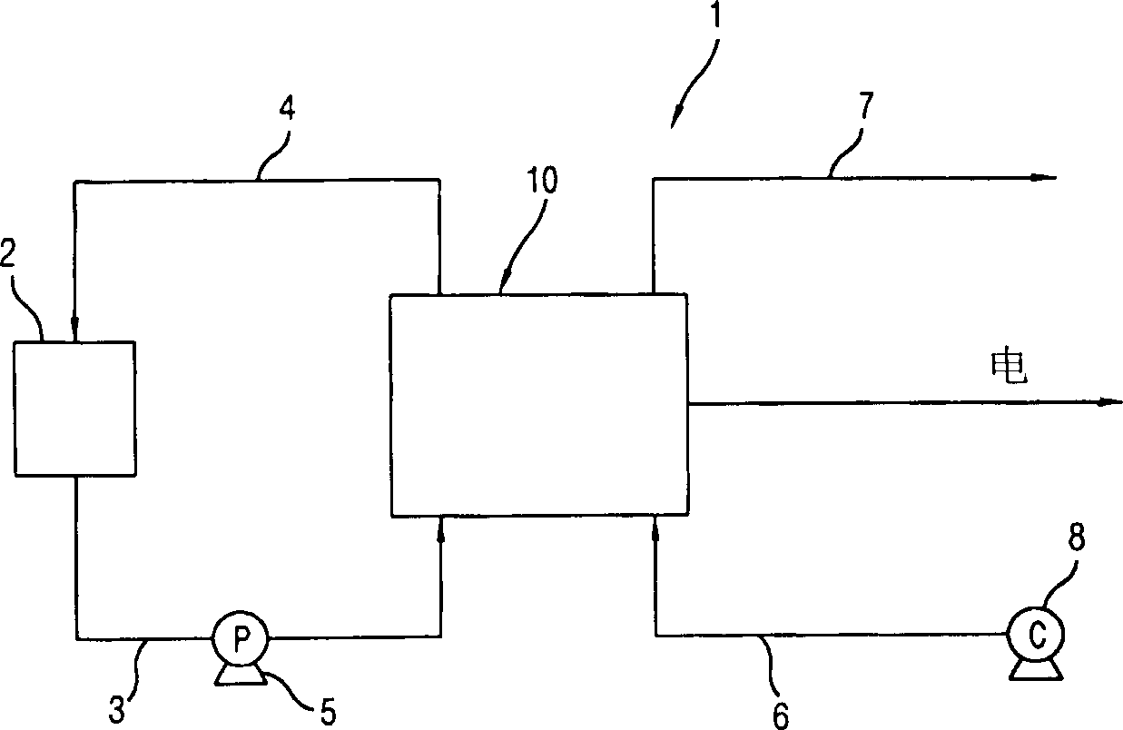
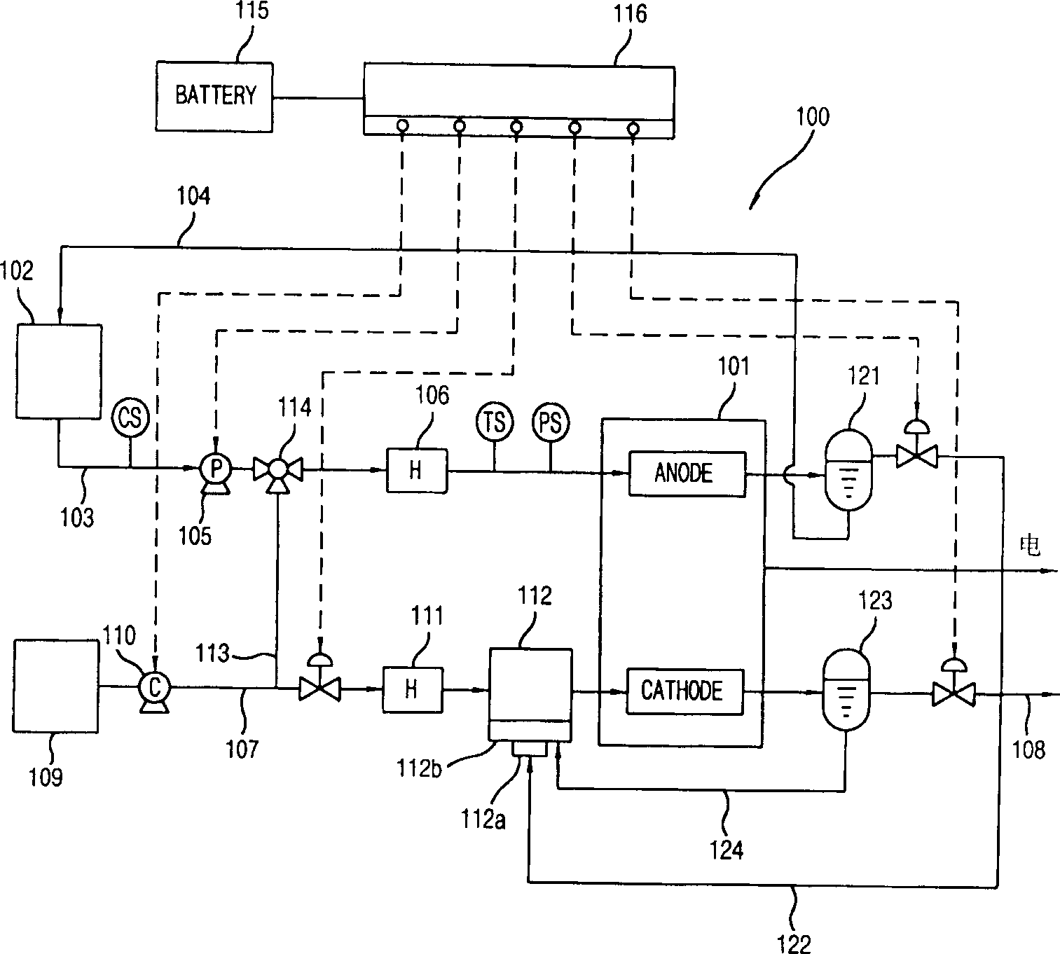
[0040] figure 2 A simple configuration diagram of a first embodiment of the fuel cell system of the present invention is shown.

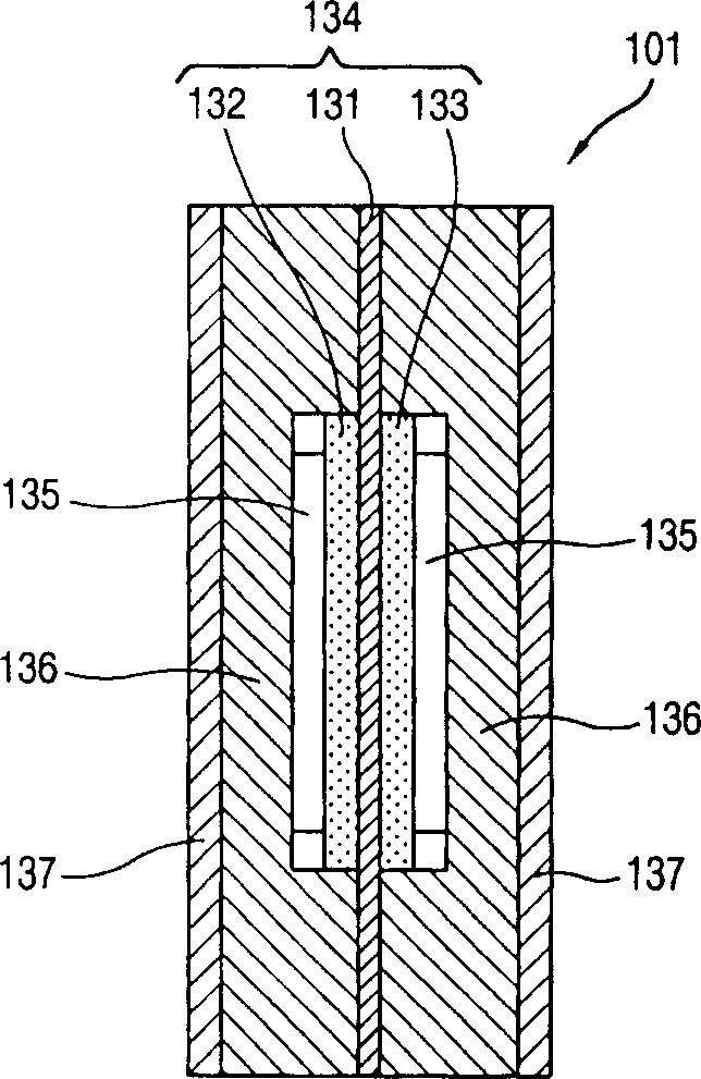
[0041] As shown in the figure, in the fuel cell system 100 of the first embodiment of the present invention, the fuel tank (FuelTank) 102 is set at a certain distance from the generator (Generator) 101, and the generator 101 passes through the BH in the aqueous solution state. 4 The electrochemical reaction of the air and the electrochemical reaction of the air is used to generate electricity; the fuel tank 102 is used to store the BH in the aqueous solution state supplied to the anode of the generator 101 4 -(boron hydride anion). The bottom of above-mentioned fuel tank 102 is connected by the anode inlet port of generator 101 and the anode inlet end that i...


PUM


Abstract

This invention provides a fuel battery system, in which, a fuel tank is linked with the anode of the generator via fuel supply lines and a fuel recovery tube, the cathode is connected with the air vent line via the air supply line, a hydrogen separator is set on the recovery tube for separating fuels and hydrogen, its recovery tube is connected with the said hydrogen separator and a blow torch of a humidifier in order to make the separated hydrogen to be the fuel of the humidifier, a water separator is set on the air vent line to separate air and water, the water recovery tube is linked with the said separator and the water tank for supplying the water separated from the separator to the tank of the humidifier to refuse the generated hydrogen and water to increases usage of the energy.

Description

technical field [0001] The present invention relates to a fuel cell system that generates electricity through the electrochemical reaction of fuel and air supplied from the outside, and furthermore, relates to a fuel cell system that can bring about the following effects: 4 - (Boron hydride negative ion) When the battery pack used as fuel generates electricity, the reacted fuel, hydrogen and water in the air can be separated and reused. Background technique [0002] Generally, a fuel cell system (FUEL CELL SYSTEM) refers to a device that directly converts energy contained in fuel into electrical energy. In the above-mentioned fuel cell system, the polymer electrolyte membrane is centered, and an anode (ANODE) ​​and a cathode (CATHODE) are arranged on both sides thereof, and hydrogen gas as a fuel is supplied to the above-mentioned anode (or called an oxidation electrode, a fuel electrode). Hydrogen produces an electrochemical reduction reaction; oxygen as an oxidant is sup...

Claims


Application Information

Patent Timeline
IPC IPC(8): H01M8/06H01M8/0662
CPCY02E60/50
Inventor 曺泰熙朴明硕李明浩黄龙俊金铁焕高承兑许成根崔鸿
Owner LG ELECTRONICS (TIANJIN) APPLIANCES CO LTD
Why Eureka
Try Eureka