Machine head structure of knitting flat machine

A technology of flat knitting machine and machine head, which is applied to knitting, flat knitting machine with individual moving needles, weft knitting, etc. It can solve the problems of not being able to drive at the same time, the limitation of knitting patterns, and cumbersomeness, so as to improve productivity and product quality. The effect of convenient density adjustment and convenient operation

Inactive Publication Date: 2004-10-06
陈焜镛
View PDF0 Cites 7 Cited by
  • Summary
  • Abstract
  • Description
  • Claims
  • Application Information

AI Technical Summary

Problems solved by technology

The bending triangle of this machine head has only one layer. When the machine head moves on the needle bed, it cannot simultaneously drive the high-heel needles and low-heel needles on the needle bed to participate in the knitting process. Only one density can be produced in one knitting row. coils, so it is impossible to form a changing pattern
[0003] The triangular bottom plate and machine feet on the head of the existing flat knitting machine are easy to wear after being used for a period of time, so that the gap between the triangular bottom plate and the needle bed of the knitting machine, and the gap between the machine foot and the guide rail of the needle bed of the knitting machine become larger, while the existing Th

Method used


Image

  • Machine head structure of knitting flat machine
  • Machine head structure of knitting flat machine
  • Machine head structure of knitting flat machine

Examples


Embodiment Construction

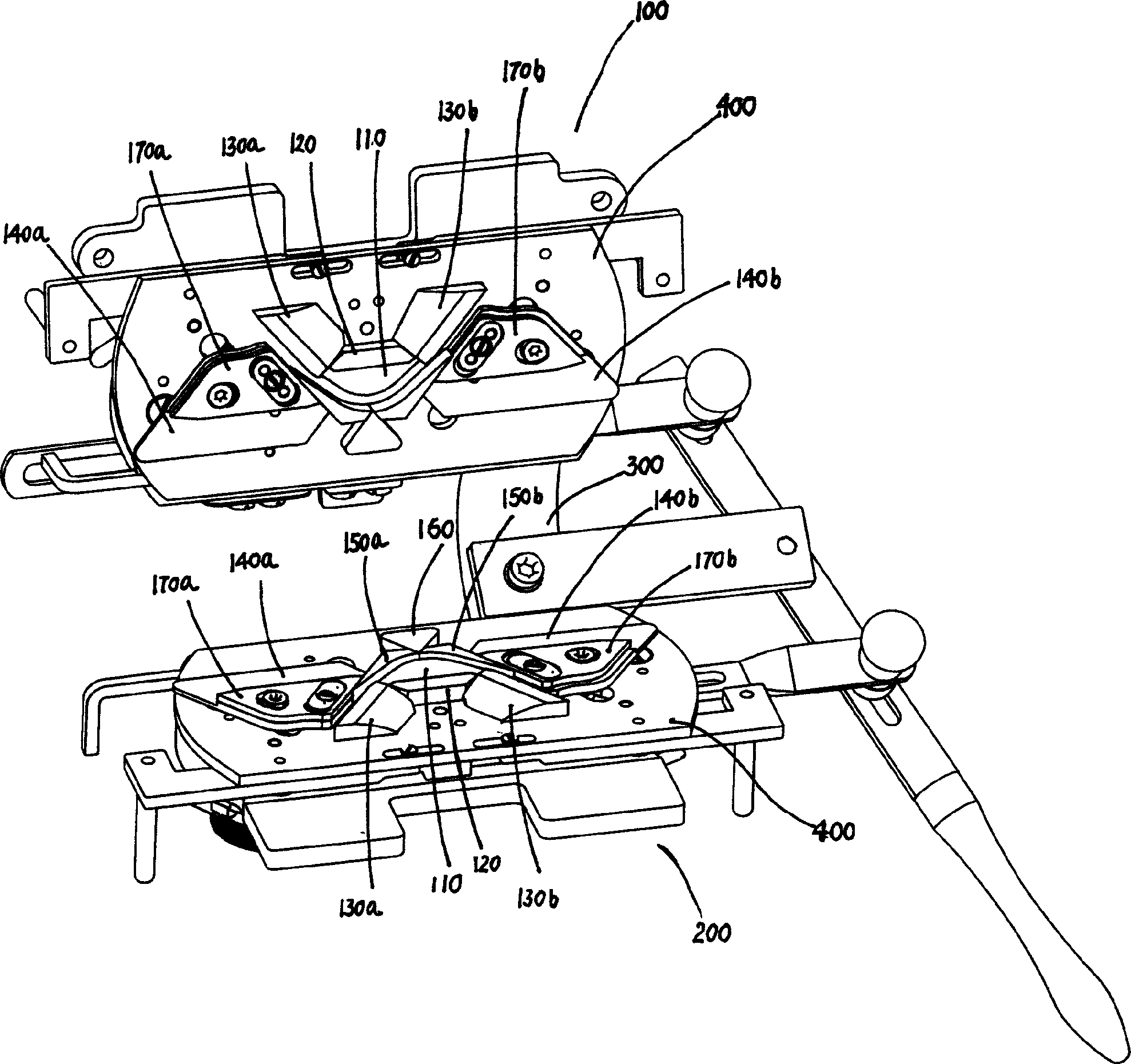
[0039] See shown in accompanying drawing 1, the present invention comprises the front head 100 that cooperates with front and rear needle bed and rear head 200 to form, and front and rear head 100 and 200 link to each other by connecting arm 300, front head 100 and rear machine The bottom plate 400 of the head 200 is respectively provided with a central jacquard cam 110, a fixed cam 120, a needle starting cam 130a and 130b, a large yarn bending cam 140a and 140b, a left and a right herringbone cam 450a and 150b and a return stitch cam 160, wherein , a needle-starting triangle 130a, a central jacquard triangle 110, one side edge of the needle-starting triangle 130a, a large yarn-bending triangle 140a, a left herringbone triangle 150a, a back-stitching triangle 160, a right herringbone triangle 150b, and a large yarn-bending triangle 140b. The side edges form a needle trajectory that meets the technical points of each weaving requirement.

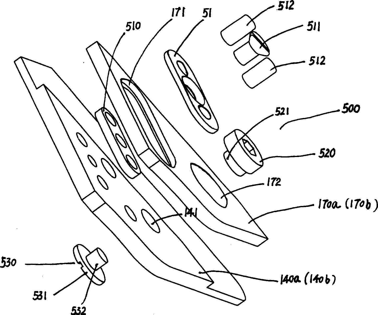
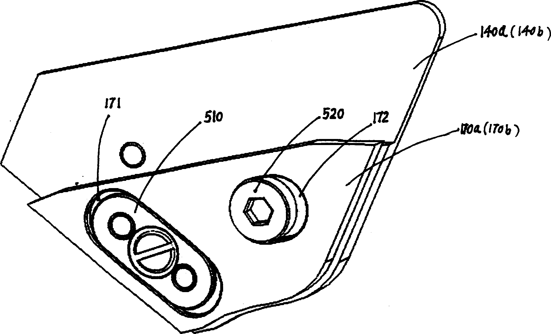
[0040] A movable yarn bending triangle...


PUM

PropertyMeasurementUnit
Angleaaaaaaaaaa

Abstract

A head structure of flak knitting machine features that on the base plate of its front and back heads there are central jacquard cam, fixing cam, needle raising cam, big knit cam, leaf and right herringbone cams, return cam, movable kit cam and regulation mechanism for generating different densities and varying pattern.

Description

Technical field: [0001] The invention relates to the technical field of flat knitting machines, in particular to a head structure of a flat knitting machine. Background technique: [0002] The flat knitting machine is one of the commonly used mechanical equipment in the knitting industry. The head of the flat knitting machine is equipped with a central jacquard cam, a fixed cam, a needle starting cam, a large yarn bending cam, left and right herringbone cams and a back stitch cam. Among them, the large yarn bending triangle can slide up and down along the outer surface of the left and right herringbone triangles to control the degree of yarn bending, the shape and size of the new loop during the loop forming process (that is, the fabric density), and whether to withdraw the loop and the degree of the loop. , a tuck can be formed when the circle is not retreated. The bending triangle of this machine head has only one layer. When the machine head moves on the needle bed, it c...

Claims


Application Information

Patent Timeline
IPC IPC(8): D04B7/00D04B15/00
Inventor 朱明星
Owner 陈焜镛
Why Eureka
Try Eureka