Driving circuit of vacuum fluorescent display

A technology for driving circuits and displays, applied to static indicators, instruments, electrical components, etc., to achieve the effect of improving convenience and reliability

Inactive Publication Date: 2004-10-06
SANYO ELECTRIC CO LTD
View PDF3 Cites 6 Cited by
  • Summary
  • Abstract
  • Description
  • Claims
  • Application Information

AI Technical Summary

Problems solved by technology

[0017] As mentioned above, for the method of adjusting the frequency of the reference clock signal, the above-mentioned problems may arise

Method used


Image

  • Driving circuit of vacuum fluorescent display
  • Driving circuit of vacuum fluorescent display
  • Driving circuit of vacuum fluorescent display

Examples


no. 1 example

[0070] ==Filament Pulse Control Unit==

[0071] As a first embodiment according to the present invention, in the case of invalidating the pulse driving signal, the filament pulse control unit 212 has a voltage to drive the grid electrode 12 and the segment electrode 13 only when they are at (hereinafter referred to as "Startup Time Period") to deactivate the function.

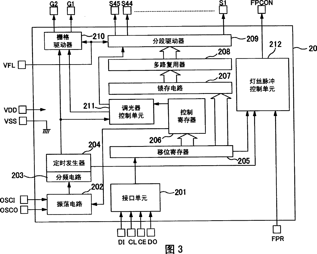
[0072] FIG. 4 shows a schematic block diagram as a filament control unit 212 according to the first embodiment of the present invention.

[0073] As shown in the figure, the filament pulse control unit 212 includes a pulse driving signal generation unit 70 , an FPD (filament pulse disable) control unit 60 and a pulse driving signal polarity setting unit 110 .

[0074] The pulse driving signal generation unit 70 generates a pulse driving signal having a predetermined duty ratio according to the internal clock signal B supplied from the timing generator 204 .

[0075] FDD control unit 60 comprises: FPDIS signal...

no. 2 example

[0103] As a second example according to the present invention, in the case of validating the pulse driving signal, the filament pulse control unit 212 has the function of setting the pulse width of the pulse driving signal according to the pulse width data and the pulse period data received from the external controller 40 or function of either one of the pulse periods.

[0104] In order to describe the above functions, first, embodiments of pulse width data and pulse period data will be described with reference to FIGS. 9 and 10 .

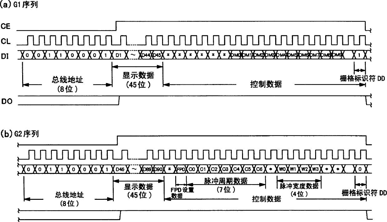
[0105] ==Pulse Width Data== FIG. 9 is a reference table related to the setting of pulse width data.

[0106] As shown, the pulse width data transferred from the external controller 40 is, for example, 4-bit serial data Wn (W0˜W3), where W0 is LSB (Least Significant Bit). The external controller 40 transmits 4-bit serial data Wn (W0 to W3) to the VFD drive circuit 20 as pulse width data, and the serial data Wn is included in the 16-bit control data...


PUM


Abstract

A driving circuit for a vacuum fluorescent display having a filament, a grid electrode and a segment electrode, the driving circuit comprising a filament driving unit for driving the filament; a grid driving unit for pulse-driving the grid electrode; and a segment driving unit for pulse-driving the segment electrode, wherein the driving circuit comprises a controlling unit for validating or invalidating the output of the filament driving unit at a proper timing.

Description

[0001] This application claims the benefit of priority from Japanese Patent Application Nos. 2003-86464 and 2003-86463 filed on March 26, 2003, the contents of which are incorporated herein by reference. technical field [0002] The invention relates to a driving circuit of a vacuum fluorescent display. Background technique [0003] A vacuum fluorescent display (hereafter referred to as "VFD") is a self-luminous display device for causing a filament to emit heat by applying a voltage thereto in a vacuum chamber to generate heat from a directly heated cathode called a filament electrons, and a desired pattern is displayed by accelerating hot electrons using a grid electrode to collide with a fluorescent material on an anode (segment) electrode and make them emit light. VFDs have excellent characteristics in terms of visibility, multi-coloration, low operating voltage, reliability (environmental resistance), etc., and are used in various applications and fields such as automob...

Claims


Application Information

Patent Timeline
Patent Type & Authority Applications(China)
IPC IPC(8): G09G3/30G09G3/06G09G3/20G09G3/22H03M1/00H03M1/82H03M1/86
CPCG09G3/2014G09G3/2007G09G2310/027G09G3/2077H03M1/86H03M1/822G09G3/22H03M1/005G09G3/30
Inventor 新井启之茂木修治木村毅德永哲也
Owner SANYO ELECTRIC CO LTD
Why Eureka
Try Eureka