Loop filtering method and loop filter

A loop filter and filter technology, applied in the field of video coding, can solve problems such as unsuitable structures, and achieve the effect of improving subjective image quality and obvious subjective image quality

Active Publication Date: 2004-10-06
HUAZHONG UNIV OF SCI & TECH
View PDF0 Cites 23 Cited by
  • Summary
  • Abstract
  • Description
  • Claims
  • Application Information

AI Technical Summary

Problems solved by technology

The algorithm proposed by Samsung is only suitable for low bit rate standards, not suitable for high-definition televisio

Method used


Image

  • Loop filtering method and loop filter
  • Loop filtering method and loop filter
  • Loop filtering method and loop filter

Examples


Embodiment Construction

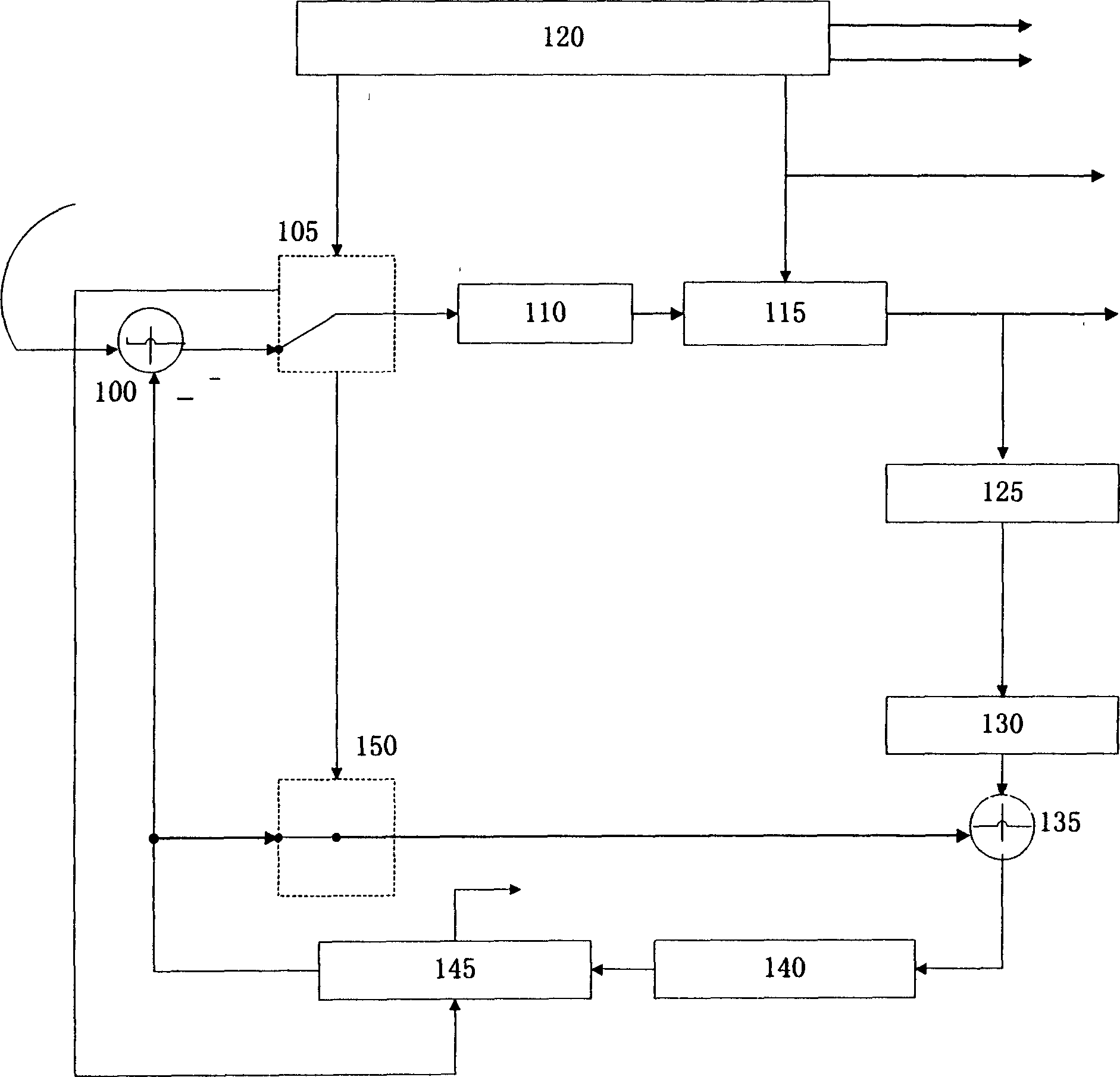
[0023] In order to describe the steps of the loop filtering method and the structure of the loop filter more clearly, the position and function of the loop filter in the entire encoder are explained first.

[0024] Such as figure 1 As shown, a video signal is input to the subtractor 100, the first switch 105 and the predictive encoder 145. The subtractor 100 subtracts the forward prediction value (ie, the motion estimation error signal) from the input video signal to obtain a prediction error, and provides the prediction error to the first switch. The first switch 105 selects the input signal according to the encoding controller 120, which is either a prediction error or an original video signal. The output of the first switch enters the discrete cosine transformer 110 (DCT), and the DCT is responsible for performing discrete cosine transform on the signal, which is the most widely used coding method in image coding. The discrete cosine transformed signal is quantized in the...


PUM


Abstract

A loop filtering method includes calculating block effect value and pixel difference, judging, and performing average filtering, difference filtering, on not filtering according to judged result. A loop filter is composed of the filter judging region consisting of image storage unit, threshold determining unit, pixel difference unit, filter judging unit, and block effect value calculating unit, and the filter executing region consisting of trigger unit, filter determining unit, average filter and difference filter. It can increase the S/N ratio by 0.20 db.

Description

technical field [0001] The invention belongs to the technical field of video coding, and specifically relates to a loop filtering method and a loop filter. Background technique [0002] In video coding, images are divided into blocks, and each block will have block effects and ringing effects to varying degrees after transformation and quantization. Typical consequences of blocking artifacts are lattice and trapezoidal noise. This type of noise will make the edges of the image noticeable or even blocky areas. Ringing noise causes a ringing effect in the image from the upper left corner of the block to the lower right corner of the block, causing multiple displayed images to overlap. [0003] The appearance of block effect is mainly caused by the quantization error caused by block processing during quantization. It has two different manifestations depending on the image content within the block range, mainly trapezoidal noise and lattice noise. [0004] Keystone Noise: App...

Claims


Application Information

Patent Timeline
IPC IPC(8): H04N7/24H04N11/04
CPCH04N19/176H04N19/82
Inventor 朱光喜文强田晓华金欣刘文予喻莉王曜
Owner HUAZHONG UNIV OF SCI & TECH
Why Eureka
Try Eureka