Fan monitoring device and its monitoring method

A monitoring device and fan technology, applied in pump control, non-variable pumps, machines/engines, etc., can solve the problems of high cost and achieve high real-time performance, simple design, and flexible design

Inactive Publication Date: 2004-10-13
HUAWEI TECH CO LTD
View PDF0 Cites 24 Cited by
  • Summary
  • Abstract
  • Description
  • Claims
  • Application Information

AI Technical Summary

Problems solved by technology

[0013] The invention provides a fan monitoring device and its monitoring method to solve the problem of high cost caused by the use of proprietary large-scale integrated chips in the prior art

Method used


Image

  • Fan monitoring device and its monitoring method
  • Fan monitoring device and its monitoring method
  • Fan monitoring device and its monitoring method

Examples


Embodiment Construction

[0030] The fan monitoring device and monitoring method proposed by the present invention are described in detail in conjunction with the accompanying drawings and embodiments as follows:

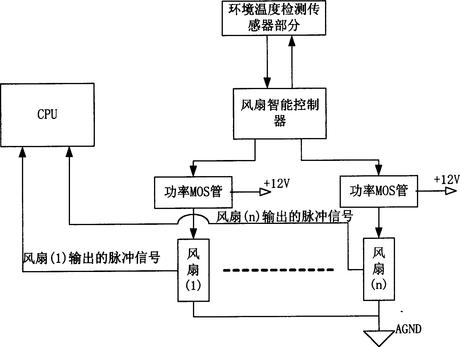
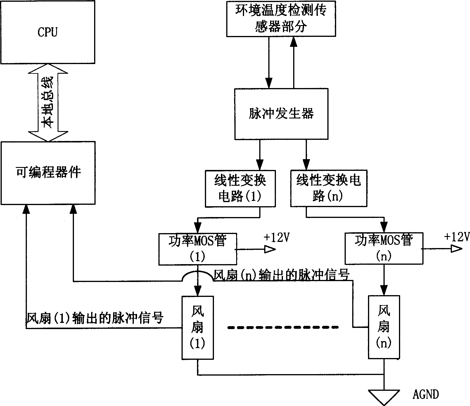
[0031] The composition of the embodiment of the fan monitoring device for communication equipment of the present invention is as follows figure 2 As shown, it includes: a central processing unit CPU (of the available device system itself), an ambient temperature detection sensor, N power MOS tubes connected to N fans respectively, and a power MOS tube connected between the ambient temperature detection sensor and the power MOS tube A pulse generator and a linear conversion circuit, and a fan speed measurement circuit based on a programmable device (available in the device system itself) connected between the CPU and the fan.

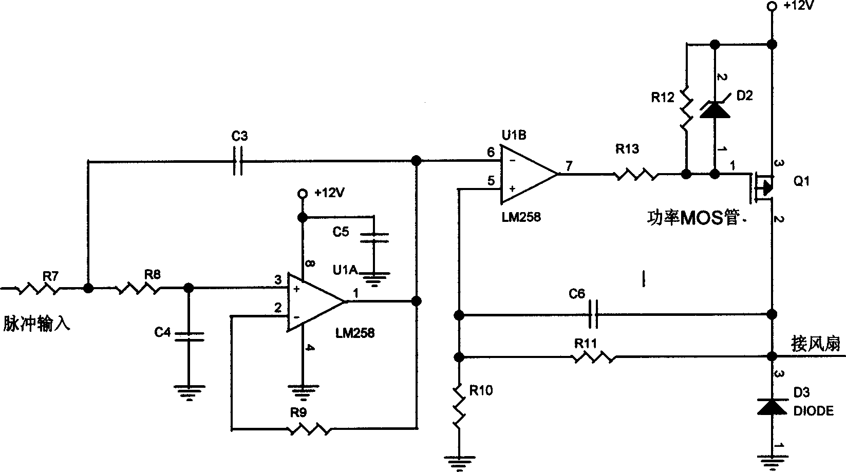
[0032] The core device of this embodiment is the pulse generator, which uses the TC648 chip of MICROCHIP Company to complete the function of converting the variable e...


PUM


Abstract

The present invention belongs to the field of equipment temperature monitoring technology, and relates to a fan monitoring device and its monitoring method. Said device includes environment temperature detection sensor, N power MOS trasistors respectively connected with N fans and CPU, programable fan rotating speed measuring circuit connected between CPU and fan, pulse generator connected between environment temperature detection sensor and power MOS transistor and linear conversion circuit. Said invention also provides the action of every the above-mentioned component, and said invented fan monitoring device can be used in various communication equipments.

Description

technical field [0001] The invention relates to the technical field of temperature monitoring, in particular to a fan monitoring device and a monitoring method thereof. Background technique [0002] In many large-scale equipment, because many of the components will generate a lot of heat, in order to ensure the normal operation of the equipment, multiple fans must be used to cool the equipment by forced air to reduce the operating temperature of the system. However, a fan rotating at high speed will generate noise, and the decibel number of the noise increases with the increase of the air cooling intensity, so how to solve the fan noise is very critical in the design of large equipment. [0003] For example, in communication equipment, since the traditional fan itself does not have the function of intelligently monitoring its intensity, it is necessary to design the monitoring of the fan in the equipment to minimize the noise of the fan. At present, a common practice is to ...

Claims


Application Information

Patent Timeline
Patent Type & Authority Applications(China)
IPC IPC(8): F04D27/00
Inventor 沈明杨昌金于海
Owner HUAWEI TECH CO LTD
Why Eureka
Try Eureka