Cutting method of optical element

A technology of optical elements and cutting methods, which is applied in metal processing and other directions, can solve the problems of high cost and rough cutting surface, and achieve the effects of low cost, small tool wear and cost saving

Inactive Publication Date: 2004-10-20
HONG FU JIN PRECISION IND (SHENZHEN) CO LTD +1
View PDF1 Cites 4 Cited by
  • Summary
  • Abstract
  • Description
  • Claims
  • Application Information

AI Technical Summary

Problems solved by technology

[0005] In order to overcome the shortcomings of rough cutting surface and high cost in the cutting method of optical elements in the prior art, the present invention provides a cutting method of optical elements with fine cutting surface and low cost

Method used


Image

  • Cutting method of optical element
  • Cutting method of optical element
  • Cutting method of optical element

Examples


Embodiment Construction

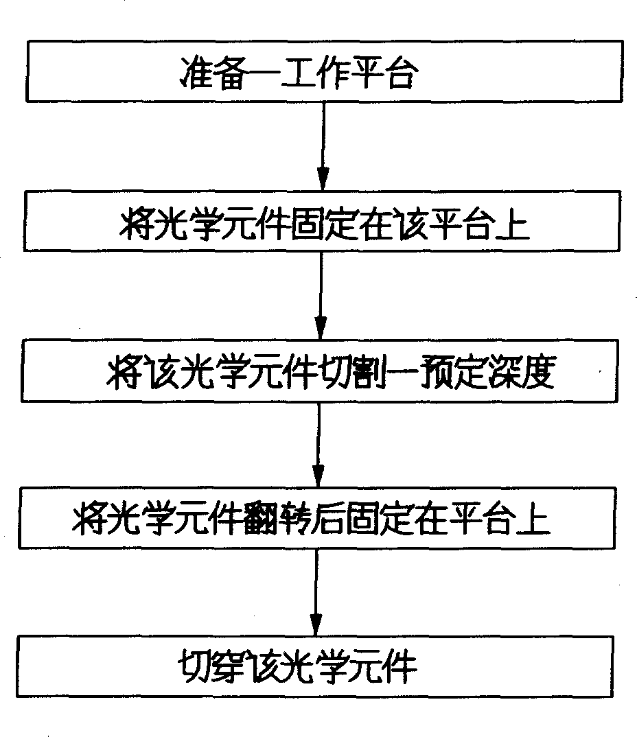
[0013] The flow chart of the cutting method of the optical element of the present invention is as figure 1 shown. First prepare a working platform; fix the optical element to be processed on the platform; cut the optical element to a predetermined depth; turn the optical element over and fix it on the platform; cut through the optical element along the relative cutting position , that is, the cutting of the optical element is completed.

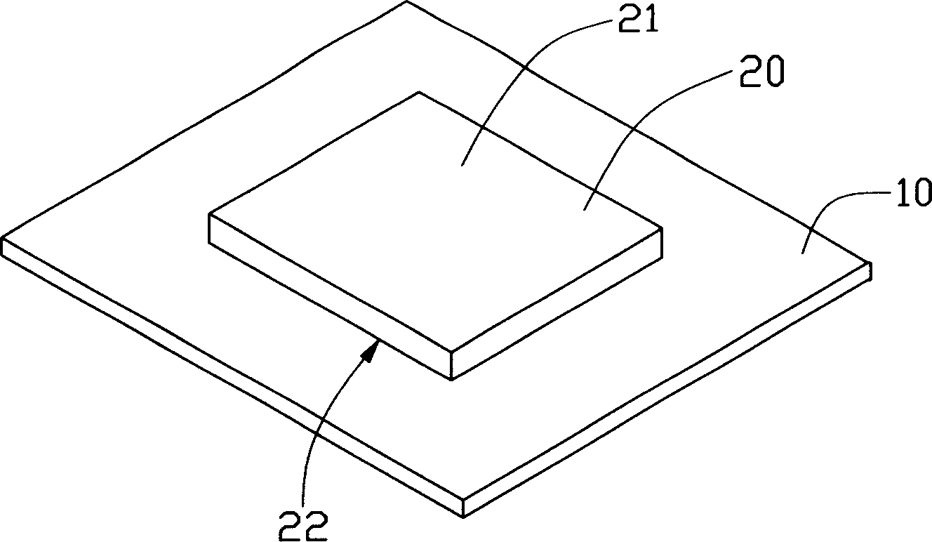
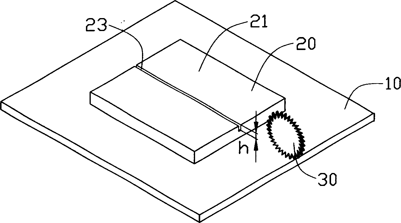
[0014] Figure 2 to Figure 5 It is a three-dimensional view between the elements during the cutting process of the optical element of the present invention. like figure 2 As shown, first a working platform 10 is prepared, and then the optical element 20 to be processed is fixed on the working platform 10 . Wherein the working platform 10 can be a hard and non-deformed glass platform with a smooth surface; a hard and non-deformed stainless steel platform can also be used, which has excellent surface smoothness. The optical element 20 has...


PUM


Abstract

A method for cutting optical element includes such steps as providing a bench, fixing an optical element to be cut onto the bench, cutting it to a predefined deepth, turning over the optical element, fixing it onto the bench, and cutting the residual tickness.

Description

【Technical field】 [0001] The invention relates to a cutting method of an optical element, in particular to a cutting method of an optical element with a fine cutting surface. 【Background technique】 [0002] Cutting is a common process. With the advancement of technology, the requirements for the cutting end face after cutting are getting higher and higher. For optical components, their end faces need to have good precision to reduce the loss of light during transmission, that is, the end faces of optical components should have good finish, flatness and uniformity. [0003] In the prior art, knives are often used to cut optical components, because the surface shear force of the knives is different during the cutting process, and surface roughness such as chipping and edge chipping is likely to occur on the cutting surface, which has a great impact on the quality of optical components. In order to eliminate the surface roughness, additional processing, such as grinding and po...

Claims


Application Information

Patent Timeline
IPC IPC(8): B26D1/04B26D3/08
Inventor 刘铭萱
Owner HONG FU JIN PRECISION IND (SHENZHEN) CO LTD
Why Eureka
Try Eureka