Tracking error detecting device
A tracking error and detection device technology, applied in the configuration/installation of the head, instrument, data recording, etc., can solve the problems of tracking error signal accuracy deterioration
- Summary
- Abstract
- Description
- Claims
- Application Information
AI Technical Summary
Problems solved by technology
Method used
Image


Examples
Embodiment 1
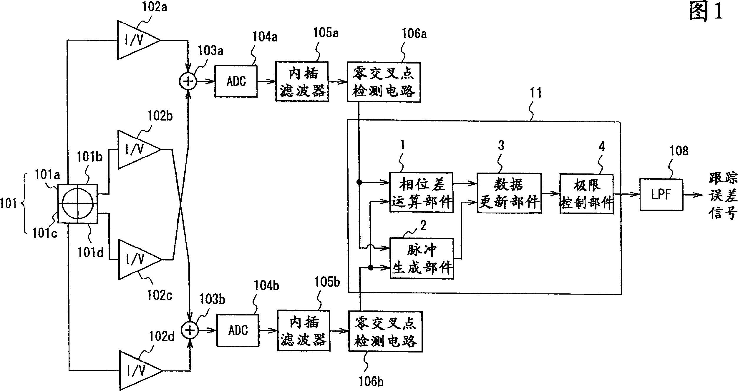
[0066] Below, use Figure 1, figure 2 The tracking error detecting device according to Embodiment 1 of the present invention will be described.
[0067] FIG. 1 is a block diagram showing an example of the configuration of a tracking error detection device according to Embodiment 1 of the present invention.
[0068] In Fig. 1, the tracking error detection device based on the present invention consists of a photodetector 101, current-to-voltage converters 102a-102d, two first and second adders 103a, 103b as signal generators for generating signal sequences, a first And the second analog-to-digital converter (ADC) 104a, 104b, the first and the second interpolation filter 105a, 105b, the first and the second zero-cross point detection circuit 106a, 106b, the phase difference detection circuit 11, and the low-pass A filter (LPF) 108 is formed. In addition, each constituent element other than the phase difference detection circuit 11 of the tracking error detection device accordin...
Embodiment 2
[0085] Next, a tracking error detecting device according to Embodiment 2 of the present invention will be described.
[0086] Fig. 4 is a block diagram showing an example of the configuration of a tracking error detection device according to Embodiment 2 of the present invention.
[0087] In Fig. 4, the tracking error detection device of the present invention consists of a photodetector 101, current-voltage converters 102a-102d, the first and the second adders 103a, 103b, the first and the second analog-to-digital converter (ADC) 104a, 104b, edge detection circuit 21, the first and the second interpolation filter 105a, 105b, the first and the second zero-cross point detection circuit 106a, 106b, phase difference detection circuit 22, and low-pass filter (LPF) 108 constitute . In addition, each constituent element other than the edge detection circuit 21 and the phase difference detection circuit 22 of the tracking error detection device according to Embodiment 2 of the presen...
Embodiment 3
[0106] Next, a tracking error detecting device according to Embodiment 3 of the present invention will be described.
[0107] Figure 7 It is a block diagram showing an example of the configuration of a tracking error detection device according to Embodiment 3 of the present invention.
[0108] Figure 7 Among them, the tracking error detection device of the present invention includes: a photodetector 101, equipped with a photosensitive element of reflected light of a photosensitive spot, and outputs a photocurrent corresponding to the light-sensing amount of each photosensitive element; the first to fourth current-voltage converters 102a ~102d, convert the photocurrent output of the photodetector 101 into a voltage signal; the first to fourth analog-to-digital converters (ADC) 104a~104d, according to the voltage obtained by the first to fourth current-voltage converters 102a~102d signal to obtain the first to fourth digital signal sequences; the first to fourth interpolatio...
PUM
| Property | Measurement | Unit |
|---|---|---|
| length | aaaaa | aaaaa |
Abstract
Description
Claims
Application Information