

Earth auger of making concrete pile
A technology for auger drilling rigs and concrete piles, applied in rotary drilling rigs, earthwork drilling, rotary drilling, etc., can solve problems such as complex structures of auger drilling rigs, and achieve the effects of preventing hole collapse and increasing compaction
- Summary
- Abstract
- Description
- Claims
- Application Information
AI Technical Summary
Problems solved by technology
Method used
Image

Examples
Embodiment Construction
[0015] The present invention will be described in detail below in conjunction with the accompanying drawings and embodiments.
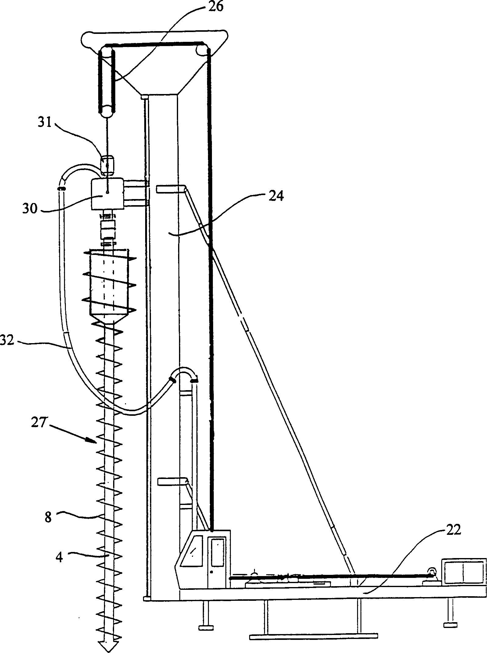
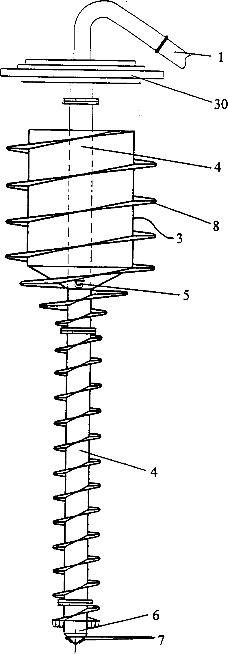
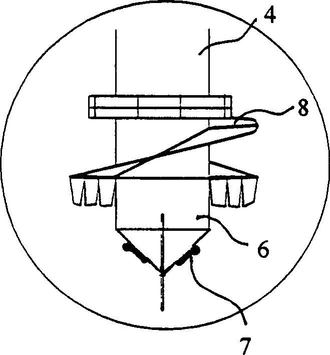
[0016] figure 1 Shown is the schematic view of the auger drilling machine for forming concrete piles of the present invention, the auger drilling machine includes a chassis 22, a drilling tower 24 arranged on the chassis 22 and a drilling tool installed on the drilling tower 24 through a lifting system 26 on the drilling tower 24 27. The drilling tool 27 is provided with a hollow drill rod 4 with a helical blade 8. The top end of the hollow drill rod 4 communicates with one end of the concrete feed pipe 32 through the power head 30 in a relatively rotatable manner, and the other end of the concrete feed pipe 32 It is connected with the concrete pump to supply concrete into the hollow drill pipe. The motor 31 drives the power head 30 to rotate through the reducer not shown in the figure, thereby driving the hollow drill pipe 27 to rotate for drilling o...
PUM
 Abstract
Description
Claims
Application Information