Optical coder
An optical encoder and spectrum technology, applied in the field of optical encoders, can solve the problems of unfavorable cost, peeling off of bonded parts, etc., and achieve the effect of excellent resistance performance
- Summary
- Abstract
- Description
- Claims
- Application Information
AI Technical Summary
Problems solved by technology
Method used
Image
Examples
Embodiment Construction
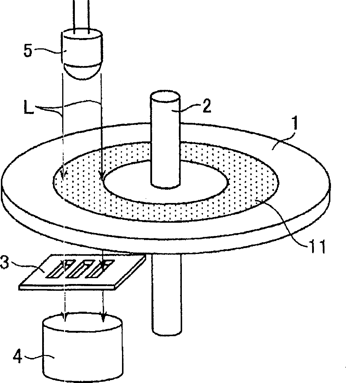
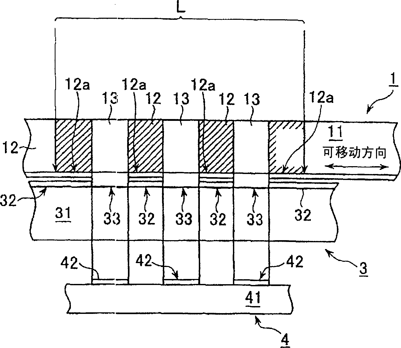
[0022] figure 2 It is a schematic view to illustrate an embodiment of the structure of the optical encoder used in the present invention. like figure 2 As explained in, the optical encoder according to the present embodiment is a rotary encoder, which consists of an encoder disc 1, a rotating shaft 2, a fixed slit member 3, a light receiving unit 4, and a light emitting unit 5 as basic components. In the light emitting unit 5, one or more light emitting elements are provided, and if necessary, a lens and the like for parallelizing the light beams are provided. Here, an infrared light-emitting diode with an emission wavelength in the range of 800 to 1000 nm is used as the light-emitting element. A code disc 1 is provided with a code grating whose features will be described later. The encoder disc 1 mounted on the rotary shaft 2 is positioned such that its encoder grating can be constantly inserted between the light emitting unit 5 and the light receiving unit 4 .
[0023...
PUM
| Property | Measurement | Unit |
|---|---|---|
| thickness | aaaaa | aaaaa |
Abstract
Description
Claims
Application Information
 - R&D
- Intellectual Property
- Life Sciences
- Materials
- Tech Scout
- Unparalleled Data Quality
- Higher Quality Content
- 60% Fewer Hallucinations
Browse by: Latest US Patents, China's latest patents, Technical Efficacy Thesaurus, Application Domain, Technology Topic, Popular Technical Reports.
© 2025 PatSnap. All rights reserved.Legal|Privacy policy|Modern Slavery Act Transparency Statement|Sitemap|About US| Contact US: help@patsnap.com


