Checkerboard shear volume reduction system

A volumetric and slicing technology, applied in the field of radioactive materials, can solve the problems of work scheduling and overall consideration of loss, reactor shutdown, time consumption, etc.

Inactive Publication Date: 2004-10-27
ATOMIC ENERGY OF CANADA LIMITED
View PDF0 Cites 0 Cited by
  • Summary
  • Abstract
  • Description
  • Claims
  • Application Information

AI Technical Summary

Problems solved by technology

Passing a vessel of this size through the containment structure of a CANDU(R) type nuclear reactor is a difficult and time consuming task requiring cranes or other heavy material handling equipment and evacuation o

Method used


Image

  • Checkerboard shear volume reduction system
  • Checkerboard shear volume reduction system
  • Checkerboard shear volume reduction system

Examples


Embodiment Construction

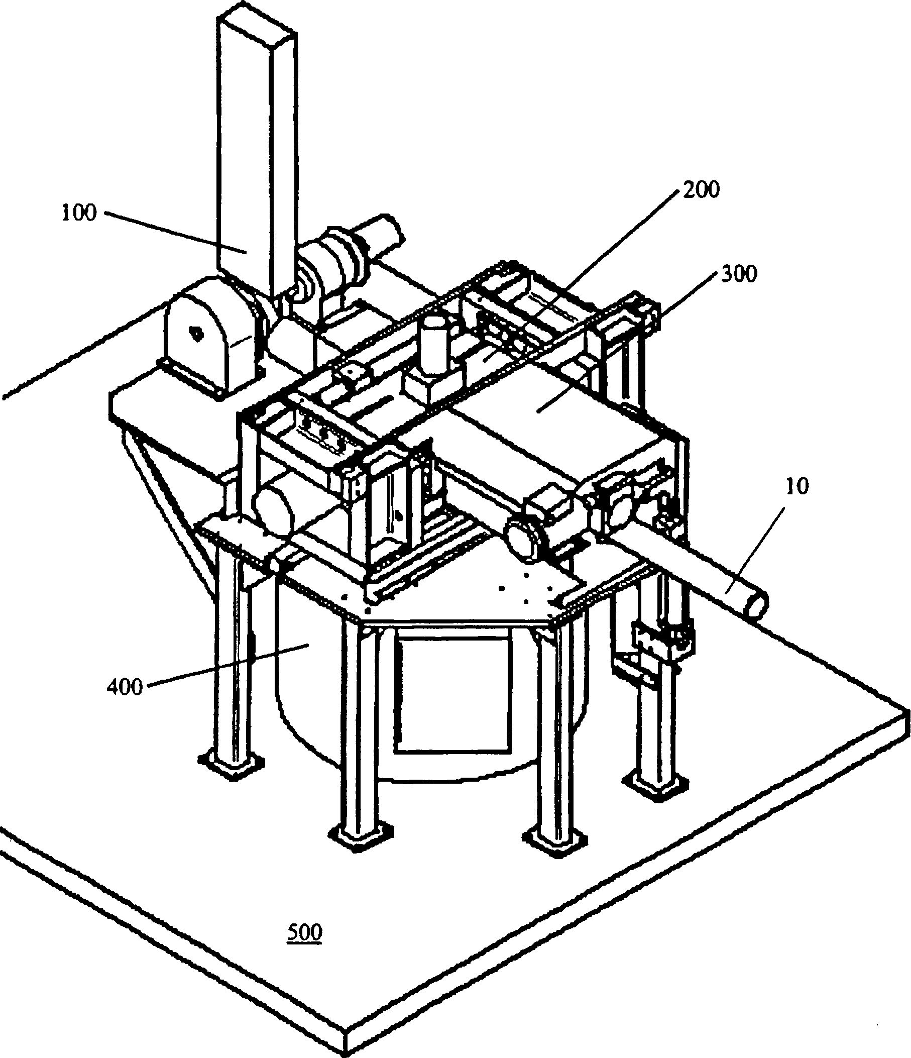
[0019] refer to figure 1 , shows a checkerboard shear volume reduction system in the present invention. The system includes a retracting unit 100 , a pressing assembly 200 , a delivery assembly 300 and a containment assembly 400 . The pressure tube volume reduction system is mounted on a work platform 500 that is movable horizontally and laterally to move between lattice sites and inward / outward to move towards and away from lattice sites (the lattice sheet) to move, and to be able to move vertically to move up and down relative to the grid area. exist figure 1 The cylindrical pressure tube 10 is shown in the position where the volume reduction takes place.

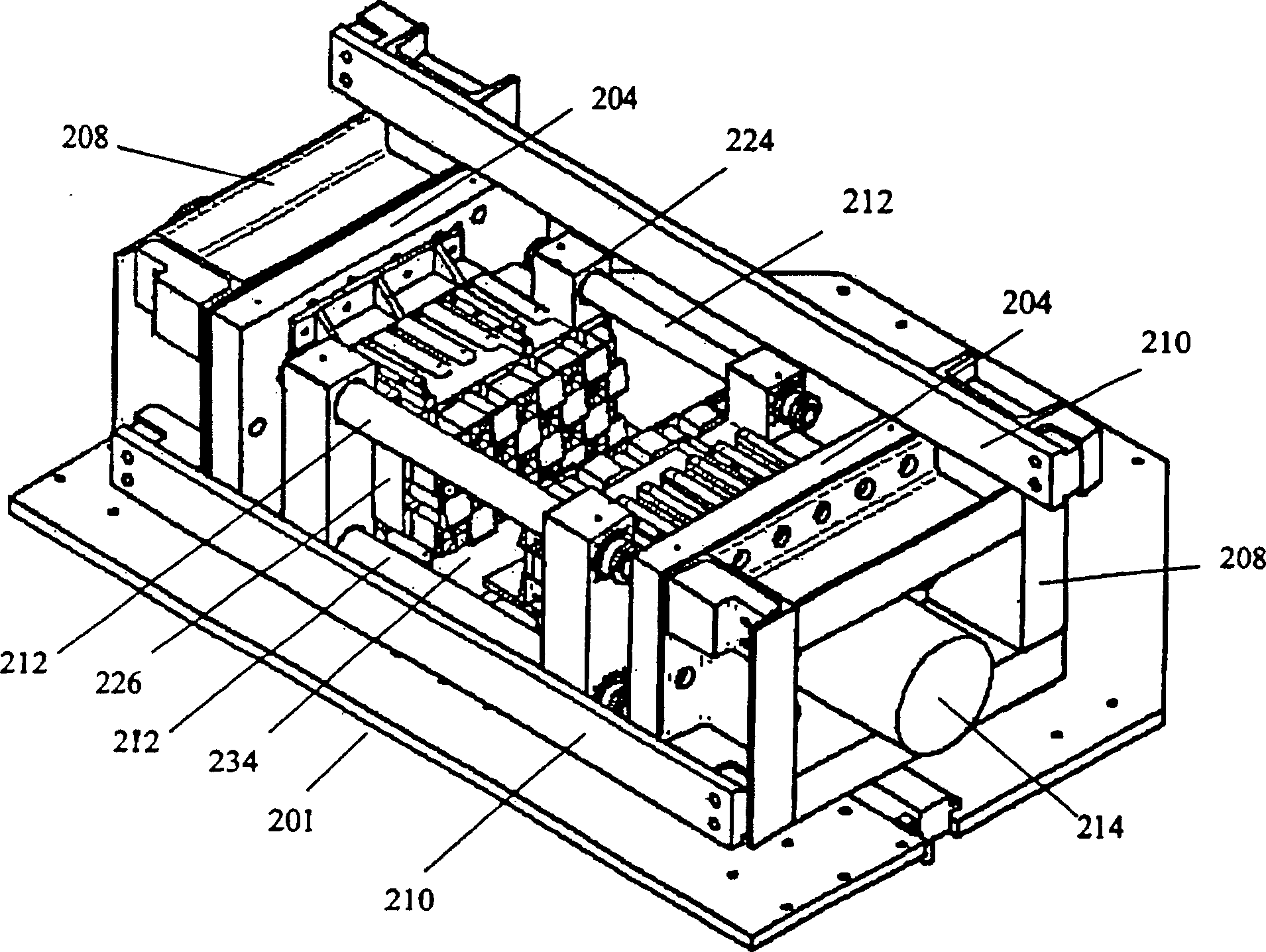
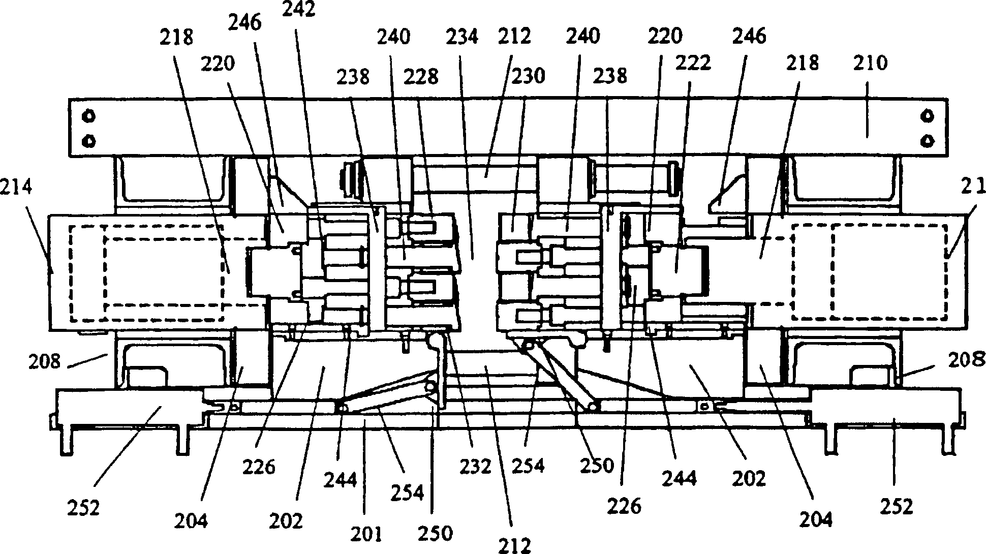
[0020] Refer below figure 2 and 3 , shows the pressing assembly 200 in more detail. The press assembly 200 includes a base 202 and an end plate 204 . The end plate 204 is relatively fixed by the box frame 208 , the bottom plate 201 and the parallel tie plates (stapes) 210 . Tie plates 210 are bolted at the four c...


PUM


Abstract

A method and apparatus for reducing the volume of a cylindrical tube for disposal by crushing flat and then shearing into small coupons. Shearing is accomplished by opposed dies having a checkerboard grid of cutting edges. The resulting coupons are preferably substantially square in shape. The invention is particularly useful for reducing the storage volume of irradiated radioactive pressure tubes from a nuclear reactor.

Description

technical field [0001] The invention relates to a method and a device for volume reduction and disposal of materials, the main field of application of which concerns irradiated radioactive substances. In particular, the present invention relates to methods and apparatus for extracting, handling and disposing of pressure tubes and heating tubes from a CANDU(R) nuclear reactor. Background technique [0002] In order to extend the operational life of the CANDU(R) nuclear reactor, extensive fuel line replacement must be undertaken. A key step in the massive replacement of the fuel lines is to remove the highly radioactive pressure and heater tubes from the reactor core. [0003] The usual procedure involves taking about 6 meters of pressure and heating pipe in one piece, or cutting it in two at their midpoint. On one side in the direction of movement of the conduits, no one is allowed around the reactor vault, which makes it impossible to carry out work in parallel and thus sl...

Claims


Application Information

Patent Timeline
IPC IPC(8): G21C19/375
CPCG21Y2002/302G21C19/375G21Y2002/301G21Y2004/40G21Y2002/206G21Y2004/30G21Y2002/501G21Y2002/304Y02E30/30
Inventor 詹姆斯·M·金克莱尔·A·考克斯
Owner ATOMIC ENERGY OF CANADA LIMITED
Why Eureka
Try Eureka