Light source of back light module

A backlight module and light source technology, applied in optics, nonlinear optics, instruments, etc., can solve problems such as insufficient uniformity of white light, and achieve the effect of shortening the distance and fully mixing

Inactive Publication Date: 2004-11-03
AU OPTRONICS CORP
View PDF0 Cites 8 Cited by
  • Summary
  • Abstract
  • Description
  • Claims
  • Application Information

AI Technical Summary

Problems solved by technology

[0006] Therefore, the object of the present invention is to provide a light source for a backlight module to solve the known pr

Method used


Image

  • Light source of back light module
  • Light source of back light module
  • Light source of back light module

Examples


Embodiment Construction

[0031] In order to make the above and other purposes, features, and advantages of the present invention more comprehensible, a preferred embodiment is specifically cited below, and in conjunction with the accompanying drawings, the detailed description is as follows:

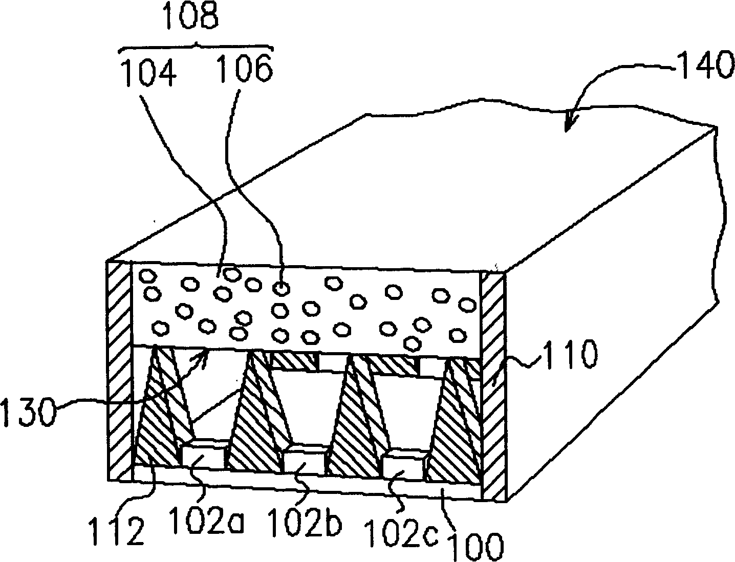
[0032] Please refer to figure 1 , which is a schematic diagram of a light source of a backlight module according to the first preferred embodiment of the present invention. The light source of the backlight module of this embodiment includes several light emitting diodes 102 a , 102 b , 102 c , a diffusion device 108 , several support members 112 and a reflector 110 .

[0033] Wherein, the LEDs 102a, 102b, 102c are arranged on a carrier 100, and the carrier 100 is preferably a reflective carrier. As for the LEDs 102a, 102b, and 102c arranged on the carrier 100, the number and manner of their arrangement are determined according to actual needs. The light emitting diodes 102a, 102b, 102c are, for example, red (...


PUM


Abstract

The light source for back light assembly includes red LED, green LED, blue LED, diffusor, support member and reflecting plate. The red LED, the green LED and the blue LED are set on a carrier; the diffusor is set over the carrier and consists of one transmitting body and powder particles dispersed inside the transmitting body. The support member is set between the diffusor and the carrier, and the reflecting plate on two sides of the carrier and the diffusor. The diffusor of the present invention mixes three kinds of color light emitted by the red LED, the green LED and the blue LED into white light.

Description

technical field [0001] The present invention relates to a light source structure of a backlight module of a liquid crystal display, and in particular to a light source structure which utilizes red light, green light and blue light emitting diodes to mix white light. Background technique [0002] In order to match the modern life pattern, the volume of video or image devices tends to be thinner and thinner day by day. Although the traditional cathode ray display (CRT) still has its advantages, due to the structure of the internal electronic cavity, the display is bulky and takes up space, and there are still problems such as radiation damage to the eyes when displaying. Therefore, flat panel displays (Flat Panel Displays), such as liquid crystal displays (LCDs), organic light-emitting displays (OLEDs), or plasma displays (Plasma Display Panels, PDPs), which are developed in conjunction with optoelectronic technology and semiconductor manufacturing technology, have gradually b...

Claims


Application Information

Patent Timeline
IPC IPC(8): G02B5/02G02F1/13357H01L33/00
Inventor 周信宏李书贤
Owner AU OPTRONICS CORP
Why Eureka
Try Eureka