Method for testing RFID chip using digital signal and radiofrequency signal transmission/identification circuit

A radio frequency signal and circuit identification technology, applied in electronic circuit testing, semiconductor/solid-state device testing/measurement, etc., can solve problems such as uneconomical, and achieve the effect of saving test cost and test time

Inactive Publication Date: 2004-11-03
爱德万测试(苏州)有限公司
View PDF0 Cites 12 Cited by
  • Summary
  • Abstract
  • Description
  • Claims
  • Application Information

AI Technical Summary

Problems solved by technology

People can use a mixed-signal tester to test, but it is uneconomical in terms of hardware loss and test time of the test itself

Method used


Image

  • Method for testing RFID chip using digital signal and radiofrequency signal transmission/identification circuit

Examples


Embodiment Construction

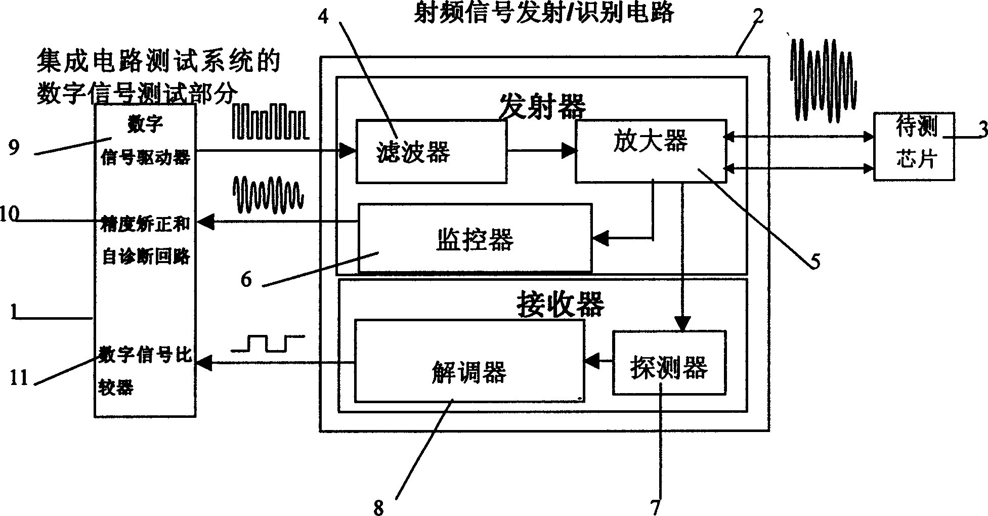
[0014] Mount the radio frequency signal transmission / identification circuit (Figure 1) module on the test circuit board, use the digital channel of the integrated circuit test system and the radio frequency signal transmission / identification circuit to generate a sine wave signal conforming to the ISO14443 standard, for example:

[0015] The voltage peak-to-peak value is 15V, the ASK modulation factor is 10%, the carrier frequency is 13.56MHz, and the data string is ALOHA (0x05, 0x00, 0x00+CRC). At this time, the monitor part starts to detect the stability of the attenuated sine wave signal in real time.

[0016] Wait for the test chip to respond, and the detector part starts to work. For example, for the above sine wave signal conforming to the ISO14443 standard, the return signal is a sine wave signal with a voltage peak-to-peak value of 15V, BPSK load modulation, and a subcarrier frequency of 847KHz. The data string is 0x50XXXXXXXXXXXXXXXXXXXXXX+CRC

[0017] Through the de...


PUM


Abstract

This invention relates to a method for testing RFID chips with digital signal and RF signal emit/identification circuit including that a digital signal generator of a test system generates a digital signal to generate a RF signal in conformity with the ISO standard by the RF signal emit/identification circuit, when the chip receives the said signal, it generates a return signal to be captured by the identification part of the RF signal emit/identification circuit and converted into a digital signal to be sent to the test system for judgment and comparison finally, thus reducing test cost and saving time.

Description

technical field [0001] The invention belongs to the technical field of integrated circuit testing, and in particular relates to a method for testing an RFID chip by using a digital signal and a radio frequency signal transmitting / identifying circuit. Background technique [0002] RFID is the abbreviation of radio frequency identification system. Compared with other types of identification systems, it has the advantages of fast identification speed, good confidentiality, not easy to be polluted by the outside world, high data density, and good readability. It is widely used in public transportation, banks, Medical and other industries have become very popular in Europe, America and other places. A typical example is the non-contact IC card. In my country, the production and use of non-contact IC card chips is still in its infancy. At present, only a few economically developed cities have carried out pilot projects in public transportation, medical insurance and other industri...

Claims


Application Information

Patent Timeline
Patent Type & Authority Applications(China)
IPC IPC(8): G01R31/28H01L21/66
Inventor 浜岛明刘旸
Owner 爱德万测试(苏州)有限公司
Why Eureka
Try Eureka