Automatic drip irrigation flow rate control switch

A switch and flow technology, applied in the field of automatic control switch devices, can solve the problems of unstable size, complex structure, inconvenient operation, etc., and achieve the effect of remarkable control effect and fast response.

Inactive Publication Date: 2004-11-24
INST OF METAL RESEARCH - CHINESE ACAD OF SCI
View PDF4 Cites 7 Cited by
  • Summary
  • Abstract
  • Description
  • Claims
  • Application Information

AI Technical Summary

Problems solved by technology

However, the drip irrigation system usually uses devices such as humidity sensors, microcomputer control, and solenoid valve drives. Complex equipment and expensive prices greatly limit its popularization and application.
[0003] Chinese Invention Patent (Application No. 86207335, Publication No. CN86207335U, Publication Date November 7, 1987) discloses a soil drip irrigation switch, which consists of a soil negative pressure sensor and an elastic film flow control component, which is controlled by soil negative pressure. The negative pressure in the sensor is actuated to control the irrigation water supply channel; Chinese invention patent (patent number 88209217.0, announcement number CN2036345U, announcement date April 26, 1989) discloses an automatic drip irrigation dripper, which consists of a soil negative pressure tube and an elastic It consists of a thin-film control flow valve. The switch and opening degree of the flow control valve are controlled by the pressure in the soil negative pressure pipe; the above two patents use a soil negative pressure sensor made of porous ceramics, which has a complex structure and is inconvenient to operate.
[0004] Chinese invention patent (patent No. 89212164.5, announcement number CN2047479U, announcement date on November 15, 1989) discloses a kind of automatic plant drip irrigation device, comprises container, hose, valve and the dropper that can be inserted into soil conveniently, also has The diverter used to expand the drip irrigation area and the sensor that can automatically control the opening and closing of the dripper according to the growth needs of the plants, that is, the degree of dryness and humidity of the soil; Chinese invention patent (patent number 91231990.9, authorized announcement number CN2127242Y, announcement date February 24, 1993 Japan) discloses a drip irrigation device with automatic humidity control, which is composed of a cylindrical bracket connected to a cuboid aqueduct, a wooden expansion block inside the bracket, a spherical valve and a spring inside the aqueduct, and a diaphragm between the bracket and the aqueduct , using the principle of wood material expanding when wet and shrinking when drying, the valve is closed or opened, thereby controlling the flow of water in the pipeline; the above two patents both use wooden expansion blocks as the sensor driving material, and their expansion coefficient is only 2 %, and the expansion and shrinkage are slow, easy to produce plastic deformation, resulting in dimensional instability

Method used


Image

  • Automatic drip irrigation flow rate control switch
  • Automatic drip irrigation flow rate control switch
  • Automatic drip irrigation flow rate control switch

Examples


Embodiment Construction

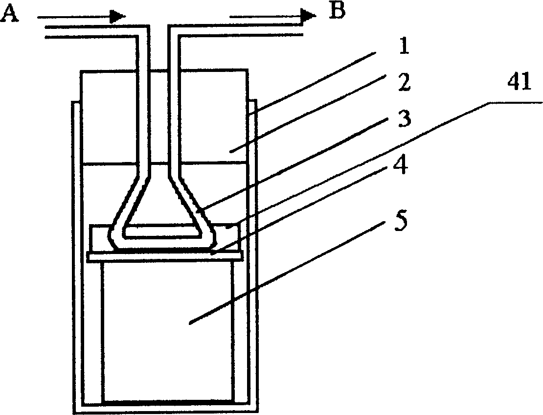
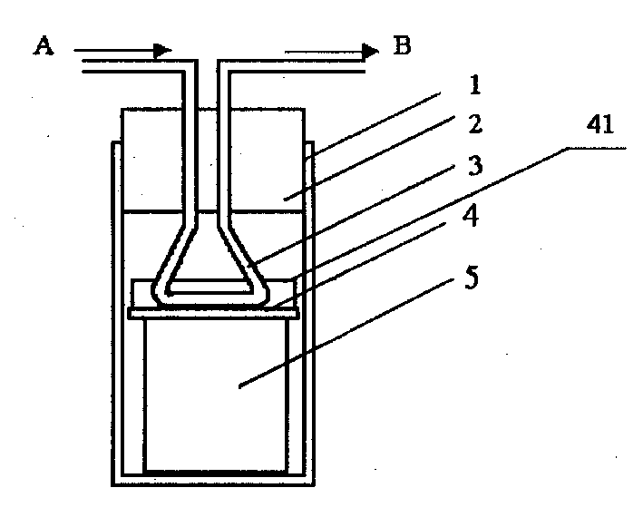
[0025] Such as figure 1 Shown is the structural representation of the present invention. The device is composed of a porous shell 1, a water-absorbing material 5, a limit top plate 4, an elastic water pipe 3, and a limit piston 2. The porous shell 1 with one end open is equipped with a water-absorbing material 5, and the top of the water-absorbing material 5 is provided with a limit top plate 4, and the elastic water pipe 3 Bend into a U-shaped structure, the bottom of the U-shaped structure is the pressure deformation end, which is in contact with the limit top plate 4, the inlet and outlet ends of the elastic water pipe 3 pass through the limit piston 2 and closely cooperate with it, the limit piston 2 and the porous shell 1 is closely matched, and the pressure deformation end is subjected to the pressure of the limit top plate 4, as shown in figure 1 The triangle shown. Arrow A is the water inlet and B is the water outlet. In the figure, the porous shell 1 is a rigid she...


PUM


Abstract

The automatic drip irrigation flow rate control switch to control flow rate based on the humidity of soil consists of porous casing, water absorption material, elastic water pipe and position limiting piston. The water absorption material is set inside the porous casing with one opened end, the U-shaped elastic pipe has its bottom pressurized end contacted with the water absorption material and its water inlet end and water outlet end passed through and contacted closely with the position limiting piston, and the position limiting piston is matched closely with the porous casing. The present invention perform adaptive regulation on drip irrigation flow rate automatically without need power supply and has fast response speed, small size and low cost, and is wide applicable.

Description

technical field [0001] The invention relates to an automatic control switch device, in particular to a switch capable of automatically controlling drip irrigation flow according to soil moisture. Background technique [0002] There are three commonly used crop irrigation methods: artificial irrigation, ditch self-flow irrigation, and sprinkler irrigation, all of which have the disadvantage of serious waste of water resources. Most of the water seeps down along the soil gap, and only a small part is absorbed by the root system of the crops. . Especially in the case of increasingly tense water resources in our country, it is of great significance to save irrigation water and promote high-tech agriculture. Drip irrigation technology only slowly supplies water to the roots of crops, while the soil between crops remains dry; it can save water to the minimum, and the water resource utilization rate can be as high as 85% to 95%. However, the drip irrigation system usually uses de...

Claims


Application Information

Patent Timeline
Patent Type & Authority Applications(China)
IPC IPC(8): A01G25/16
CPCY02A40/22
Inventor 曾尤郭敬东何冠虎周本濂
Owner INST OF METAL RESEARCH - CHINESE ACAD OF SCI
Why Eureka
Try Eureka