Cavity member

A cavity and component technology, applied to building components, building structures, floors, etc., can solve problems such as increased construction costs, high damage rate of cavity components, and easy breakage of structural bottom plates

Inactive Publication Date: 2004-11-24
湖南邱则有专利战略策划有限公司
View PDF3 Cites 4 Cited by
  • Summary
  • Abstract
  • Description
  • Claims
  • Application Information

AI Technical Summary

Problems solved by technology

However, during the handling and construction of such cavity components, the structural bottom plate is prone to breakage, so the damage rate of the cavity components is high, and the handling and construction are inconvenient, which increases the construction cost.

Method used


Image

  • Cavity member
  • Cavity member
  • Cavity member

Examples


Embodiment Construction

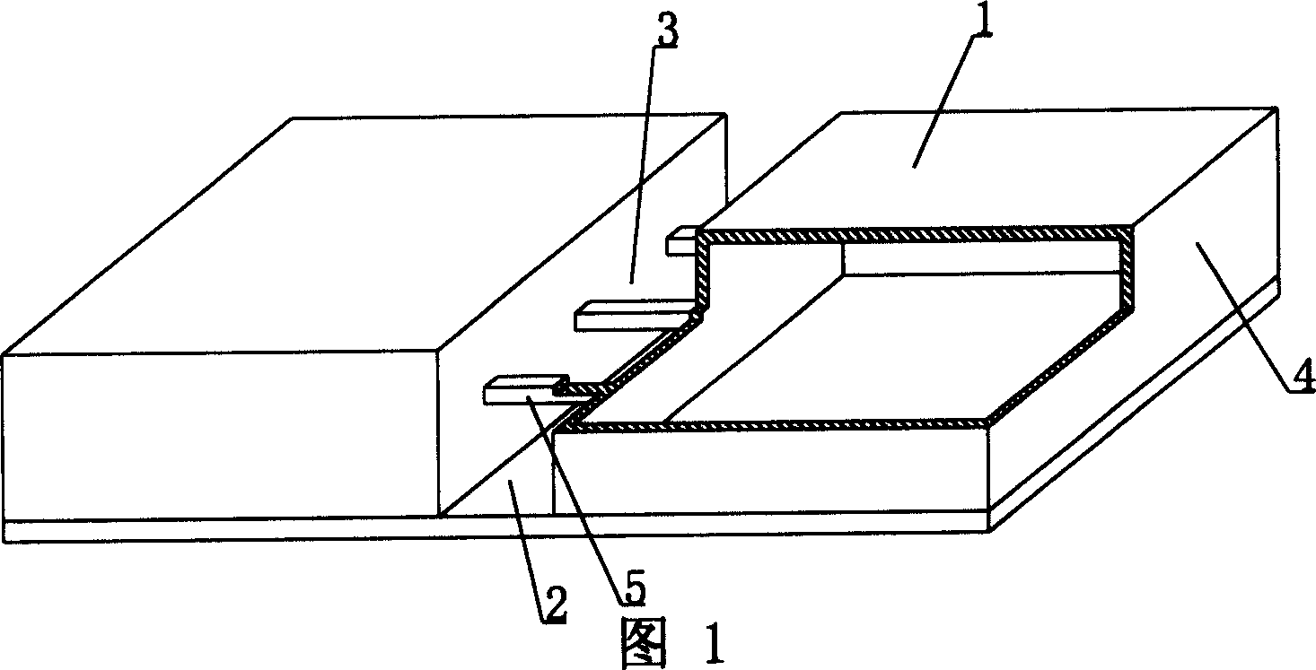
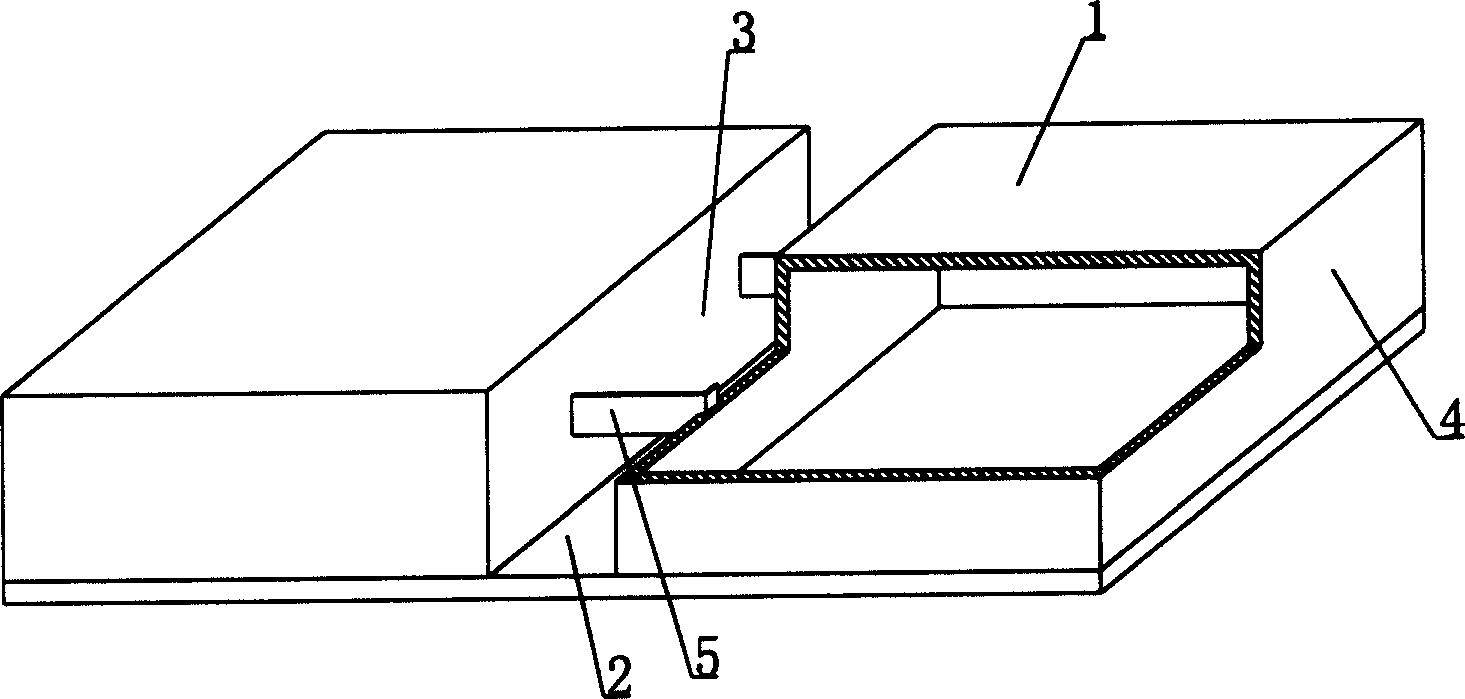
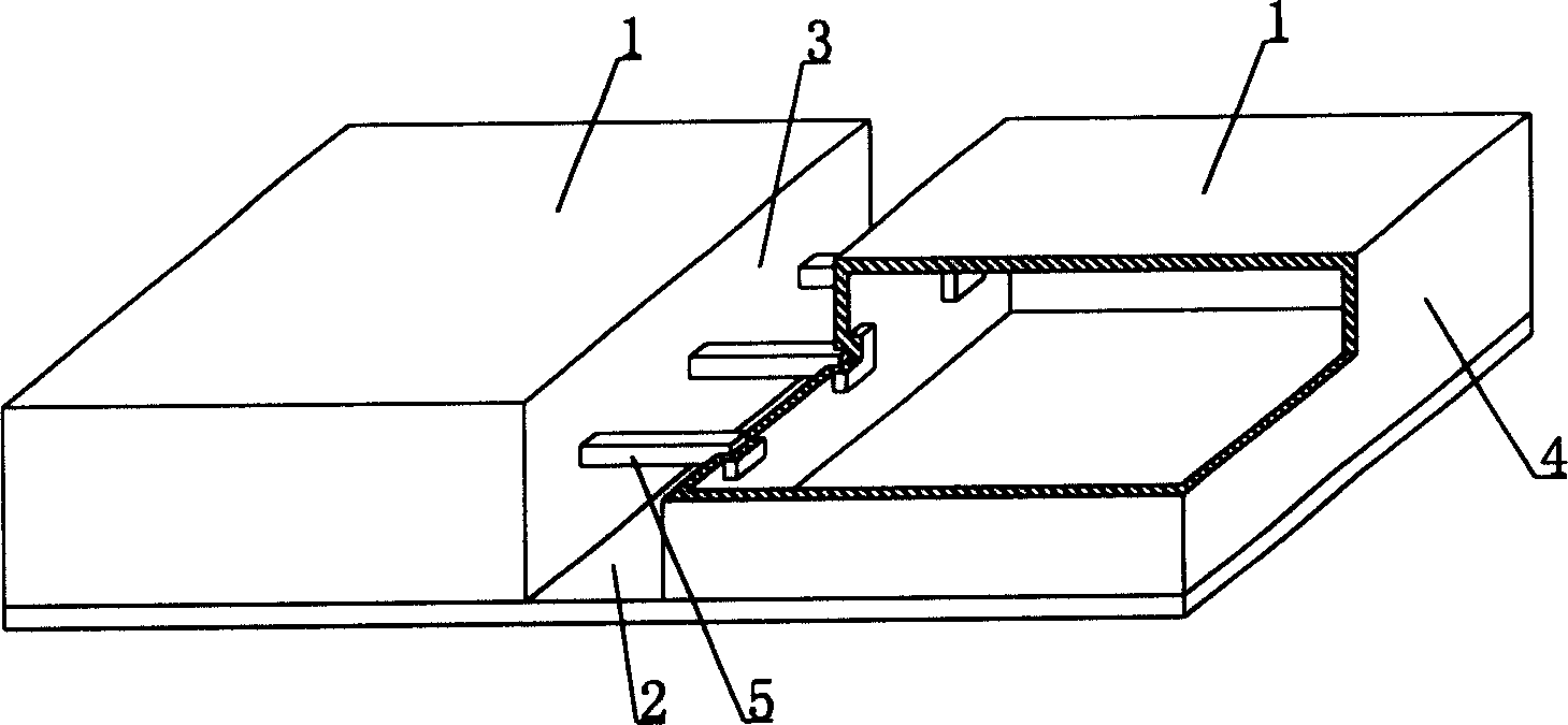
[0052] The present invention will be further described below in conjunction with drawings and embodiments.

[0053] As shown in the accompanying drawings, the present invention includes a cavity formwork 1 and a structural bottom plate 2. The cavity formwork 1 and the structural bottom plate 2 are connected as a whole, and at least two cavity formworks 1 are arranged alternately on the structural bottom plate 2. The side surface and the structural bottom plate 2 form at least one cast-in-place structural secondary rib cavity 3, and the other outer sides 4 of the cavity formwork 1 form the side formwork of the main rib or beam or wall of the cast-in-place structure, which is characterized in that the adjacent cavity At least one brace 5 is disposed in the secondary rib cavity 3 of the cavity formwork 1 to connect adjacent hollow formworks 1 to each other. Fig. 1 is the structural representation of embodiment 1 of the present invention, and among Fig. 1, 1 is cavity formwork, an...


PUM


Abstract

The cavity member includes cavity shuttering and structural bottom board constituting one integral. The present invention features that on the structural bottom board there are at least two alternately arranged cavity shutterings with one side constituting in-situ cast secondary ribbed cavity together with the structural bottom board and the other sides constituting in-situ cast side formwork main rib, beam or wall. There is at least one support part to connect the adjacent open web cavities to raise the strength and rigidity of the cavity member, raise the impact performance. The present invention is suitable for floor slab, roofing, base slab, wall and open web bridge of in-situ or pre-stressed reinforced concrete.

Description

(1) Technical field [0001] The present invention relates to a cavity member. (2) Background technology [0002] At present, most buildings with brick-concrete structure and reinforced concrete structure use prefabricated hollow slabs as floor slabs, which have the advantages of fast construction speed and low cost. However, because there is no firm connection between two adjacent prefabricated hollow slabs, only cement mortar is used to fill the joints, so the integrity is poor, which is not conducive to earthquake resistance, and cracks and water seepage often occur in the gaps. In order to solve the above problems, many buildings adopt the method of cast-in-place concrete floor slabs (solid and hollow). Although the problems of earthquake resistance and cracking have been solved, a large number of templates are used during construction, which not only increases the cost, but also slows down the construction speed and prolongs the construction period. deadline. Applicatio...

Claims


Application Information

Patent Timeline
Patent Type & Authority Applications(China)
IPC IPC(8): E04B5/32E04B5/36
Inventor 邱则有
Owner 湖南邱则有专利战略策划有限公司
Why Eureka
Try Eureka