Cemented carbide broach and broaching machine

A cemented carbide, alloy steel technology, applied in the direction of broach, broach, linear broach, etc., can solve problems such as insufficient strength

Inactive Publication Date: 2004-12-01
NACHI-FUJIKOSHI
View PDF2 Cites 14 Cited by
  • Summary
  • Abstract
  • Description
  • Claims
  • Application Information

AI Technical Summary

Problems solved by technology

[0005] However, even with this configuration, when the broach has a small diameter, the broach suffers from problems similar to those of the combination broach described above
More specifically, in a small-diameter broach, the shaft diameter of the rear control portion including the small-diameter portion clamped by the broach clamping portion (storage body 24) is small, so there is a possibility that, in the broaching will not be strong enough to overcome compressive loads during milling

Method used


Image

  • Cemented carbide broach and broaching machine
  • Cemented carbide broach and broaching machine
  • Cemented carbide broach and broaching machine

Examples


Embodiment Construction

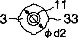
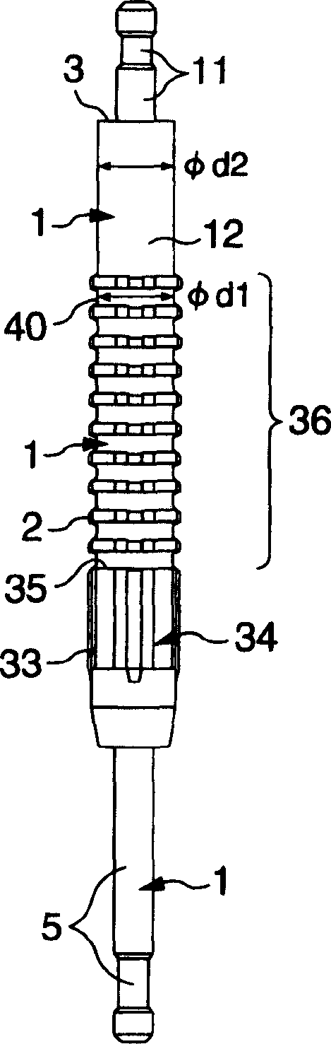
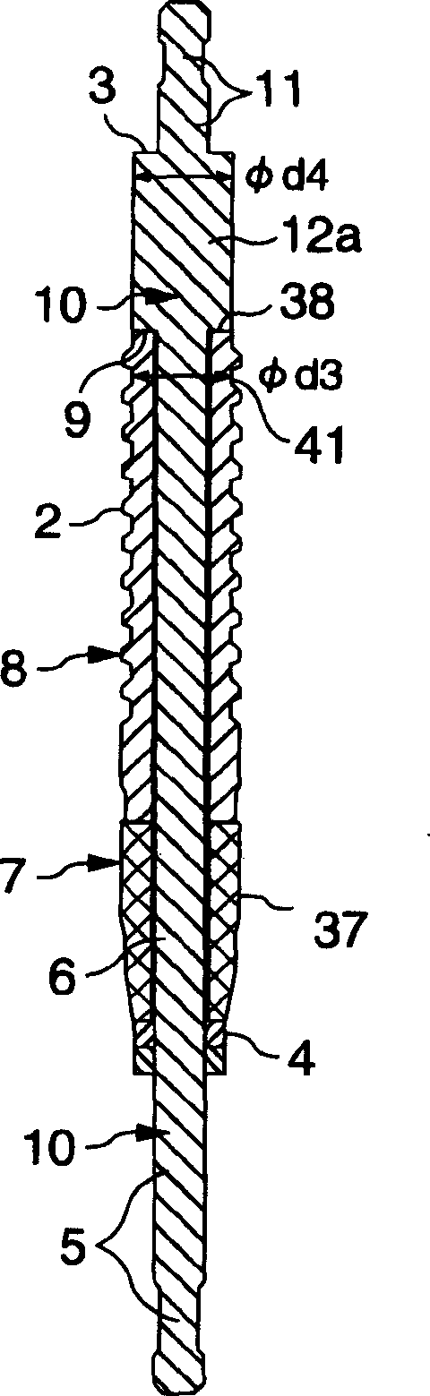
[0025] Figure 1a with Figure 1b A cemented carbide broach according to the first embodiment of the present invention is shown. The broach has an elongated body 1 made of cemented carbide material. On the main body 1, the front control part 5, the cylindrical part 34 behind the front control part 5, the broach cutting edge part 36 behind the end part 35 of the cylindrical part, the broach cutting edge The cylindrical extension 12 behind the portion 36 and the rear control portion 11 behind the cylindrical extension 12 .

[0026] The cylindrical portion 34 is formed with a plurality of guide portions 33 in its outer circumference. The broach cutting edge portion 36 is provided with a plurality of cutting edges 2 . The cylindrical extension 12 has a maximum outer circumference dimension to such an extent that the broach does not interfere with the workpiece to be processed, and is a portion whose outer circumference is larger than that of the rear control portion. The rear ...


PUM


Abstract

A broach has a main body of a cemented carbide material. On this main body, a front grip portion, a cylindrical portion following the front grip portion and provided with a plurality of guide parts in its outer periphery, a broach cutting edge portion following an end of the cylindrical portion and having a number of cutting edges, and a cylindrical extension following the broach cutting edge portion and having a maximum outer periphery dimension to such an extent that the extension does not interfere with a work are integrally provided. On an end surface of the cylindrical extension, a load receiving shoulder is formed, which leads to a rear grip portion including a small-diameter part and is orthogonal to or inclined with respect to a broach axis. The load receiving shoulder has a sufficient area to bear a cutting load. A broaching machine grips the rear grip portion with its load receiving surface abutting against the load receiving shoulder of the cemented carbide broach. The broach, even when having a small diameter, does not suffer from an insufficient tensile strength of the front grip portion.

Description

technical field [0001] The present invention relates to push-type or compression-loaded carbide broaches and broaching machines for reaming spline holes, square holes, keyways, round holes, etc. Background technique [0002] A cemented carbide broach has a cutting edge made of cemented carbide material and is used for machining a material having a high hardness of 45 to 65 HRC (Rockwell hardness C scale) after hardening treatment. In this cemented carbide broach, when the control part and the cutting edge are made in one piece, the control part is made of a cemented carbide material with low tolerance for tensile or pulling load, so there is a possibility of the control part breaking question. [0003] Taking this into consideration, JP-A-2002-137118 in its accompanying drawing 1 proposes a combined broach in which the hollow cylindrical cutting edge part is made of hard alloy material and the control part is made of alloy steel. However, under this combination structure, ...

Claims


Application Information

Patent Timeline
Patent Type & Authority Applications(China)
IPC IPC(8): B23D43/02B23D37/10B23D41/04B23D43/04
CPCB23D37/10B23D43/04Y10T409/4056Y10T409/40665Y10T407/16
Inventor 角谷宗一村井康弘
Owner NACHI-FUJIKOSHI
Why Eureka
Try Eureka